
| +Home | Museum | Wanted | Specs | Previous | Next |

Friden EC-130 Electronic Calculator
Updated 9/4/2025
Friden's management realized that the days of the electro-mechanical calculator were numbered sometime in 1960, after there were rumors of work involving the development of an all-electronic calculator in Britain, as well as potential efforts in Japan. The implication that electronics could take the place of the intricate mechanical machines was huge, and potentially threatening to Friden's market leadership position in mechanical calculating machines. Friden management wanted no chance that their bread and butter business could be threatened. Something had to be done quickly to assure that Friden would enter the electronic calculator marketplace.
In 1961, Sumlock Comptometer, Ltd., set the calculator world on end when it introduced the first commercially available electronic calculator. The Anita Mark 7 and Mark 8 calculators caused many makers of electro-mechanical and relay calculators to realize that the future of calculating was with electronics. While the Sumlock Comptometer machines were not very sophisticated, they clearly demonstrated that an electronic calculator is vastly faster very quiet, and required no adjustment. Electro-mechanical calculators were noisy, slow, and had lots of moving parts that required regular maintenance to continue to operate properly. Relay calculators, while less noisy, and faster than electro-mechanical machines, also had moving parts (relays rely on mechanical movement to open and close switch contacts), and also had myriad switch contacts that wore over time and required periodic maintenance and adjustment. On top of this, relays take up a lot of space, use a lot of power, and are relatively expensive. The problem for the companies that sold electro-mechanical or relay calculators as their bread-and-butter business was that, while they had brilliant mechanical and switching engineers, they had little in the way of the electronic engineering talent needed to design a practical electronic calculator. Most of the electronics engineers were working in military, space, aviation, computer, or communications technology, and those markets snatched up all of the electronic engineers fresh out of college. This led to a shortage of electronic engineers, especially those who knew anything about solid-state (transistorized) digital design, making folks with these talents a rather rare find in the early 1960's.

Robert Ragen, 1988
Image Courtesy of Dick Ahrens
By researching patent information, along with some first-hand information from a number of former Friden employees of the time, it has become clear that the essential contributor to the architecture and design of the Friden EC-130 was a brilliant electronic engineer named Robert Ragen. Ragen worked for Friden prior to the development of the Friden 130 on secret government-contracted electronics projects that Friden was involved in. The word is that the work involved electronic communications systems development (Data Encryption) for the "No Such Agency" organization within the US government's secret infrastructure. Those who would know details about this work, even to this day, are not forthcoming with information relating to the government projects, so one can assume that whatever the work was, it was and is still deemed critical to the defense and security of the United States. Whatever work was involved, it certainly provided Friden with some of the electronic stepping stones on the path toward developing a fully-electronic calculating machine to take over in place of the mechanical masterpieces that Friden was so famous for.

Inside of Friden Computyper Model CTS
Note Wired-Up Guts of Friden Electromechanical Calculator in Slide-Out Drawer
Friden also had some other in-house electronics expertise that had been acquired through the acquisition of a calculating-related product from Benson-Lehner Corporation. Benson-Lehner's primary business was electronic plotting machines..devices which would take tables of X and Y-coordinate data, and plot them out on paper, providing a graphical representation of the data. The calculating machine that Benson-Lehner had developed was a "side job", done more as an engineering exercise than anything else. This machine integrated a modified Friden electromechanical calculator with a solenoid-activated electric typewriter (An IBM Model B, this was before Friden had acquired Commercial Controls and its Flexowriter device) and a logic cabinet with relay and stepper switch logic, to make an automatic calculating machine that used the typewriter to input and print the results of calculations. Benson-Lehner called the machine the "Computyper". Benson-Lehner had tried in vain to market the machine, but didn't meet with much success, and decided to sell off the business unit it had created to develop and market the Computyper. Friden bought the business unit lock, stock, and barrel, including the bright engineers who developed the machine. Friden kept the Computyper name, and began making refinements to the Benson-Lehner design, creating different versions of the Computyper that had successively more features. The earlier machines were primarily designed to do accounting functions such as invoicing. While initially electro-mechanical/relay machines, the Computyper acquisition did help bring additional logic and switching theory expertise, as well as some digital electronics expertise to the Friden. In time, the Computyper evolved into being integrated into a newer-design Flexowriter, essentially using a small-scale integrated circuit implementation of the Friden 130 calculating logic for its math processing.

Friden 6010 Computer with 6018 Disk Drive
Friden 6010 Introduced June, 1963
Along with the experience gained with the Computyper, there was also work being done on development of Friden's own small electronic computer system, which eventually became the 6010 electronic computing system, introduced in June of 1963. The 6010 was a basic computer targeted at office applications such as billing, payroll, inventory, and other accounting-related business activities. This work was done mostly in parallel with the development of the EC-130, and expertise was shared between the projects.
During the early 1960's, Friden was advertising heavily to attract electrical engineers and technicians to acquire the resources needed for the electronics projects that the company needed to staff. All of the expertise gained from hiring bright engineer; the secret electronics work for the government; the evolution of the Computyper; along with the early work on Friden's own computer, provided the internal expertise necessary to attack the problem of developing an entirely solid-state desktop electronic calculator.
At around the time that the revelation that Friden must develop an electronic calculator, the secret work for the government began to wind down. This made available some of the resources that Friden needed to jump headlong into a project to develop an all-electronic replacement for their mechanical calculators. The realization turned into action sometime in the early part of 1961. A new department was created, known internally as Department 442. Department 442 was to be responsible for Friden's electronic calculator research & development, engineering, prototyping, manufacturing, and development of documentation for the company's electronic calculators. The first thing for Department 442 was to appoint a leader. Friden's senior management designated Friden's current VP of Research and Development, Mr. Larry Robison as the driver for the project. Robison had a lot of experience with Burroughs, working in its computer division for quite some time prior to coming to Friden, and thus understood a lot about developing complex digital systems. Robison assigned Bob Ragen as the leader of the electronic calculator development team. Ragen quickly put together a team of other Friden engineers and craftsmen who were put to task of developing a prototype of the Friden electronic calculator. The official start of the project, which had Friden internal project number 516, was July, 7 1961.
A list of the initial desired specifications were put together.
One of the first things that was identified was it was desired that
all of the working registers of the machine be displayed continuously.
Doing so with Nixie tubes (the predominant
numeric display technology of the time) would result in a huge display
(Friden wanted the display to have four rows of thirteen digits plus sign indication). Such a display
would be very expensive, and make the machine much larger than desired, even with the smallest Nixie
tubes available at the time.
It was decided that some other form of display would be required.
The thought was that a TV-like Cathode Ray Tube (CRT) display would be best to meet the display requirements. However, the skills to
develop the complex mix of digital and analog technology to create such
a display system did not exist within Friden, the timeline was very tight
such that trying to develop a team to tackle the problem simply wasn't
plausible.
The lack of the skills necessary to create a display system for the calculator
became a critical path for Friden's calculator development project.
To address the issue, sometime shortly after the project started, Robison
reached out to the Stanford Research Institute(SRI) Computer Techniques Laboratory for
assistance in the development of an electronic display system utilizing a
CRT, which was to be used for the display in an all-electronic desk calculator
that Friden was developing. Robison had dealt with SRI during his time at
Burroughs, and knew that SRI had the engineering talent to develop a display
that would meet Friden's needs. SRI had extensive experience in the
development of display systems, as they had done work developing specialized
display systems for the US military and NASA. SRI determined that the
project was feasible, and agreed to take on the project at a cost of $75,000.
As deliverables, SRI would provide full documentation of the system at the
circuitry level, as well as providing a proof of concept implementation that
was capable of displaying four lines of numbers on the display.
The proposal from SRI was developed by two brilliant SRI engineers,
Jack Bialik(7/20/1924-1/4/2010) and Milton
Adams. Bialik joined SRI in December of 1955, and his work was primarily
involved with automation of corporate and military data processing
and communications systems through the use of computers. One of his
early, as well as historically noteworthy projects, was being
part of the development of the
ERMA system for under contract to GE for Bank of America. ERMA was a
sea-change in the world of banking, with bank drafts (checks) encoded with
account information in a magnetic ink at the bottom edge of the checks,
along with a machine that operators could use to transcribe the amount of
the check into the same magnetic ink characters such that computers could
read the checks and automatically post them the the appropriate account
at lightning speed.
Milt Adams was also involved in the ERMA project, and later, he was
a team member on the project that developed
Shakey,
the first autonomous robot using early Artificial Intelligence software systems
acting as the robot's brain.
The SRI display system proposal was promptly accepted by Friden.
Bialik was appointed as the project leader for SRI Project #3747. Friden's specifications stated
that a display system
would be based on a 1 1/2" x 5" x 10" CRT that would support the display
of four registers of 27 figures each. Friden had also specified that the
construction of the display must be completely solid-state (using transistors)
other than the Cathode Ray Tube (CRT) itself. The system was also specified
to be as cost-effective as possible, as well as consuming a practical minimum
amount of physical space.
Bialik assembled a team of four engineers
(Dave Condon, Dale Masher(4/14/1929-3/30/2014), Don Ruder, Bill Stevens)
along with himself, to
create the display system prototype. The project went very smoothly, and in
early 1962, a month ahead of the date in the proposal, three prototype
systems were delivered to Friden. The prototype consisted of a cabinet
with chassis containing a large number of small circuit boards that
made up the logic to generate the display. Along with the logic circuitry,
there was a section that contained the high-voltage drive circuits.
Lastly, a magnetic drum contained the data to be displayed by the system.
The display prototype did not perform any type of calculation, it only
took the data on the drum, organized as coded digits, and displayed it
on the scope tube. The project went so well that in June of 1962,
SRI cut a check to Friden for $4,444.62 as a refund on the $75,000 payment
that Friden had made for the project.
Friden's legal department felt that the display system
was a concept that should be patented. The display system that Bialik and
his team had developed had some significant innovation in its design which
led to the system being much less complex (and thus less expensive to build)
than display systems that had been developed in the past.
In the span of less than two years, an
agreement was made between SRI and Friden for the patent rights for the
display system to be assigned to Friden. In late 1964, Bialik, who at the
time was doing contract work for the US military in France, traveled to the US
Embassy in Paris to sign the affidavits of assignment to provide Friden
with the patent rights for the display system. US Patent number
3,430,095
was filed in July of 1965, with Bialik, Dale Masher, and Bill Stevens as the
inventors, and Friden Calculating Machine Co. as the assignee.
The EDTC-1 Prototype "Calculator", January, 1962
While SRI was working on the display system, engineers at Friden were
busily working on the calculating electronics for the calculator. Near the
end of 1961, a prototype system was completed, utilizing SRI's
display system. The prototype consisted of electronics
that fit in a box somewhat larger than the size of a desk-side filing
cabinet. Sitting on top of this box was a console that provided
the user interface for the calculator, consisting of a keyboard and the
cathode ray tube (CRT) that provided the display. This initial prototype
utilized a magnetic drum (Bryant Model C-105) to both generate the master
clock frequency for the prototype (via a dedicated pre-recorded timing track),
and storage of the working registers. While useful for
a prototype, a magnetic drum simply is not practical for a desktop calculator.
The Bryant drum was physically large enough to preclude any kind of
desktop packaging. It was also quite power-hungry, noisy, and not well
adapted to an environment where the calculator may need to be
moved around (magnetic drums were shock sensitive, and could also be thrown
out of alignment if moved while operating, or while spinning up or down
when the power was turned on/off). Some other form of storage would need
to be used in the actual product.
The magnetic drum-based prototype was designated "EDTC-1". EDTC is presumed
to stand for "Electronic Desk-Top Calculator",
though this is not known positively. The prototype initially did not appear
to actually be able to perform math operations, although the keyboard did
have math operation keys. The prototype, if it could do math, did not
appear to utilize the Reverse Polish Notation (RPN) four-level stack
architecture of the production calculator. The hints to these appearances
come from internal Friden photos dated January of 1962 that show the
prototype machine in operation, as well as a detailed-enough photo of the
keyboard. The photos shown here could possibly be the demonstrator of
the display system provided to Friden by SRI, as it very closely resembles
what is described in the patent from a physical standpoint.
The author suspects that all of the indications that the stack architecture
was not considered as part of the display system design because SRI's charter
was to develop a display system, not a calculator. The arithmetic
functionality and stack architecture were Friden's responsibility, and given
the design stated in the display system patent, there is no reason to think
that the system as apparently embodied in the photos could not be
augmented to add in the math functionality (perhaps initially using the
architecture implied by the keyboard keys, and later modified to use the
stack architecture) added in as the arithmetic processing system logic was
designed by Friden calculator engineering.
The Display of the EDTC-1 Prototype "Calculator", January, 1962
The display on the EDTC-1 prototype system, while resembling the display
rendition on the production calculator (using the same Westinghouse 5DEP1
CRT as the production calculator, as described in the patent, as well
as similar digit rendition), is clearly
not a result of any kind of math operations having been performed, especially
the second line from the top, which has blank spaces interspersed with zeros.
The display in the photo from shows shows four lines of up to 25 digits.
The patent is conflicting here, in that the text states that 25 digits are
stored for each of the four registers on the drum, yet a pictorial diagram
(Figure 17) showing the layout of the digits on the CRT shows 24 digits.
The author suspects that the diagram is incorrect given the photo clearly showing
25 digits per line.
The top register on the prototype display shows the content of storage register
#1, and the second from the top register is storage register #2. The third
line from the top is the accumulator register, and lastly, the bottom line
on the display is the entry register, all as stated by the patent. This
description is also a clear indication that there was no stack architecture
in mind when the prototype was developed, though the display system design
does not preclude the use of a stack architecture.
The Keyboard of the EDTC-1 Prototype "Calculator", January, 1962
The keyboard shown on the prototype may only be a mockup, as if these
photos are of the embodiment of the system outlined in the patent, there
appears to be no way to enter numbers into the registers stored on the
drum. The patent does not describe any means to enter data into the display
system. It is suspected that there was some kind of external
fixture that could be attached directly to the drum that was used to write
the timing tracks, as well as pre-recording a sequence of digits (or blank
spaces) that would be presented on the display of the prototype as shown
in the photos.
The keyboard of the prototype has controls for two
store/recall registers, labeled [TRANSFER #1], [TRANSFER #2], [RECALL #1],
and [RECALL #2], which, as indicated in the display system patent,
refer to the top two lines of the display, a clue that these two
registers are not a part of a stack architecture.
The existence of the [FIRST FACTOR] key appears to have the purpose of
entering the first number in multiplication or divide functions, also
somewhat (though not positively) eliminating the notion of a stack
architecture on the prototype. The [←] and [→] keys do not
appear to be related to decimal point positioning, as there is no sign
of a decimal point on the keyboard, nor in the display. Perhaps these
keys were intended to be used for moving an implied "cursor" within the
entry register, with the thought being that they could be used to correct
erroneously entered digits.
A view showing the Bryant C-105 Magnetic Drum Located in the Base of the EDTC-1 Prototype
The magnetic drum pictured above is physically and logically much larger
than is necessary to store the information required for the display system
prototype, not to mention an actual calculator. The Bryant C-105 magnetic
drum used in the display system prototype was Bryant's "utility" drum, made for
general purpose use, storing approximately 400,000 bits (or the equivalent
of 50K-bytes today) with the drum rotating at the standard speed of
3,600 RPM. A half-speed version of the drum was available that spun
the drum at 1,800 RPM, which would reduce the speed of the data coming
off the drum and result in half the amount of storage, or roughly
200,000 bits. The use of this drum in the display prototype was
overkill in terms of the capacity needed for the prototype, but
it was an "off-the-shelf" item from Bryant, making it easy to get, and
likely one of the least expensive drum memory systems that Bryant
offered.
Bryant Computer Products, a division of Ex-Cell-O Corporation, was a
Michigan-based pioneer in the field of large-capacity, high-speed magnetic drum
and fixed disc storage systems. Magnetic drums became a primary storage
device for small and large-scale computer systems in the 1950's through
the mid-1970's because of their high-speed and high capacity (compared
to magnetic tape, the commonly used mass-storage in computers of this
time frame). Bryant built a sizable and successful business designing and
manufacturing add-on storage systems for IBM, Control Data, Digital Equipment
Corp., Burroughs, and other computer systems manufacturers. In most cases, the
magnetic drum served as a fast-access store that was used for storing
data that had been read in from magnetic tape for processing, as well as
for storing temporary information used in the processing of the data.
Once the data had been processed (for example, sorting the data alphabetically)
it would be written back out to magnetic tape for report generation and
future reference. Along with their business in the computer systems
market, Bryant also made storage systems for specialized electronics
such as radar and air-traffic control systems, digital storage for
high-resolution graphic display systems, buffer storage for devices such
as high-speed printers, and many other situations where a fast-access,
large-capacity storage system was embedded as part of a larger digital
data system.
Had Friden's calculator gone to market using a magnetic drum instead
of the magnetostrictive delay line, it's likely that Friden would have
contracted with Bryant to custom design and manufacture a much smaller
magnetic drum system more suitable to fit within the "desktop" calculator
package that Friden had in mind. It isn't known for sure at this point
if Friden ever intended to use a magnetic drum as the storage medium
for the working registers of the calculator. It is known that Friden
had an internal research project to develop a reliable and low-cost
magnetostrictive delay line storage element was underway beginning in the
early part of the 1960's, so perhaps the calculator was intended
to use a delay line all-along, and the magnetic drum was just used by
SRI as a non-volatile way to store the characters to be displayed on
the prototype display system. Magnetostrictive delay line storage was
vastly less expensive than any drum or disc-based storage system. A
magnetostrictive delay line has no moving parts, making it
more reliable than a magnetic drum, as well as being physically
considerably smaller in size. As Wyle Laboratories found out with their
WS-01 electronic calculator that used a small rotating magnetic disc
for its working register storage, the use of magnetic rotating memory
in an electronic calculator that is likely to be moved around in an office
or laboratory space, is an invitation to dreaded "head-crash" that can
be caused by moving a rotating memory system while the medium is still
spinning due to gyroscopic effects. Wyle Labs ended up redesigning
the WS-01 to use a magnetostrictive delay line to create the much more
reliable WS-02 calculator. In the case of Friden and their calculator, it's
most likely due to the cost involved for a custom magnetic drum, as well
as the possibility of reliability issues, that the magnetostrictive
delay line was determined early-on in the project as being the storage
system of choice for what became the Friden EC-130.
Photo of the large-scale delay line-based prototype version of the EC-130 Calculator, known internally as EDTC-3
The calculator electronics are in the lower chassis, with the keyboard and
CRT display and its drive electronics in the smaller unit sitting on top.
Another view of the EC-130 large-scale prototype, with Robert Ragen in the foreground and possibly Carl Herendeen holding a circuit board.
The early prototype machine shown in the photos above replaced the magnetic
drum with a magnetostrictive delay line, which was
much less costly and not nearly as temperamental as the magnetic drum.
These proof of concept prototype calculators were far from
practical for sale, but it served to demonstrate
the concept -- Friden had what it took to build an all-electronic calculator.
This large-scale prototype had all of the functionality of the what would be
the production calculator, including RPN logic, CRT display, magnetostrictive
delay-line storage, and transistorized construction.
Diagram of the prototype predecessor to production Friden 130 (From US Patent #3546676)
Once the large-scale delay-line based prototype was debugged and working
reliably, the next task was to shrink
the cabinet of components that made up the electronics of the machine down
to a practical and usable desktop-sized unit. A couple of factors that
contributed to making this job a little easier were that the electronics
in the prototype were designed more for development than production.
Components were not tightly packed, circuit boards had wiring only on one
side, and interconnections were widely spaced. Another factor was that the
prototype was hand-made, which generally makes for a less space-efficient
design. After all, a prototype is made to show that a concept is workable
-- the effort is placed on making the idea a reality, rather than trying
to optimize it for manufacture. In a mass-produced calculator, the space
between components can be dramatically reduced, circuit boards can have
wiring on both sides, and interconnections can be made much more dense.
This is where another problem developed. Friden did not have much experience
making the complex circuit boards that were required to reduce the machine
down to a desktop package. Friden needed to be able to manufacture circuit
boards with traces on both sides of the board. This means that there has
to be a way to provide connections through the circuit board to
allow circuitry and traces on one side of the board to connect to traces
on the other side. Such connections are called feed-throughs. For the small
and fairly simple circuit boards used in their electro-mechanical calculators
and Computypers, Friden had set up a circuit board manufacturing facility
using a rather unique machine to etch the circuit board traces.
This technology worked nicely for the simple single-sided circuit boards
needed in the electro-mechanical calculators and Computypers,
but the EC-130 needed much more complex circuit boards
with wiring on both sides of the board. This presented a problem.
When prototype boards with feed-through plated holes were put through
the circuit board machine, they tended to short out the machine.
As it worked out, the etching machine was used to make the
single-sided boards in the EC-130's power supply, but due to the
problem with feed-throughs, the logic boards of the calculator were farmed
out to a specialty firm that had the necessary equipment to manufacture
the calculators logic circuit boards.
Larry Kramer, Friden Chief Draftsman (right) and Dick Ahrens, Electronics Engineer(left) pouring over
the (huge) master schematic for the Friden 130
In March of 1963, the first version of
the calculator, all packaged into a desktop-sized unit, was ready,
and exhaustive testing was begun. A disturbing problem was found where the
calculator would inexplicably and randomly deliver incorrect results.
Intense efforts went into finding the problem, which was finally traced to
the high voltage section of the electronics (related to driving the CRT
display). High electrostatic charge levels would build up, causing
discharges that would make the calculator malfunction intermittently.
Given that these calculators were expected to deliver accurate results all
of the time, such a problem was intolerable. This, and a few other
issues that were found during the shakedown, delayed the formal introduction
of the EC-130 to the public by almost six months. This delay led to a
number of other companies developing solid-state desktop electronic
calculators to beat Friden to product introduction, including Hayakawa
Electric (Sharp) in Japan, and IME in Italy.
The First Pre-Production Desktop Prototype Friden 130, August, 1963
There is a funny story relating to the first power-up of the prototype
calculator. This story was was related to the author by Dick Ahrens, one
of the electronics engineers that was hired on by Friden in early 1963
to work on the electronic calculator project. The story goes
that when it was time to power up the fully-integrated prototype for the
first time, a joke would be played on Bob Ragen. Ken Steward, a senior
electronics technician involved in the calculator project, hid a 20-foot
length of plastic tubing stretching from his lab bench
to the inside of the prototype calculator, such that the tubing was not
readily visible. Ragen had hooked a Variac (a variable voltage
transformer) to the prototype calculator, so that the line voltage could
slowly be ramped up to full voltage, just in case there were any
problems. The time came, and Ragen turned on the power switch on the
calculator, then slowly started turning up the voltage on the Variac. At
around the same time, Ken, who remained at his lab bench, blew a bunch
of cigarette smoke into the tube, resulting in wisps of smoke coming out
of the precious prototype calculator. Ragen went into a panic, and
frantically turned down the Variac, pulled the power cord for the calculator
out of the Variac, pulled the Variac's power cord out of the wall, and then
ran to the main circuit breaker panel for the lab and killed the power to
he entire lab. Only then was the trick revealed to Ragen, who was decidedly
not amused by the prank. The power to the lab was restored, the plastic
tubing removed, and the process of powering up the calculator was redone,
and this time, everything worked just fine. Ragen took quite some time to
forgive the conspirators that had played this joke on him.
A Friden EC-130 Tie Clip, Provided to Friden Sales and Service staff by Friden.
With the desktop prototype machine working, it was decided that
the machine needed to be shown to a few industry and trade insiders
to get an idea as to the reception for this amazing machine. At a rather
secretive event, the Friden 130 prototype was shown to a specially-selected
audience at a
business machines exposition in June of 1963. Attendees were required to
sign a non-disclosure agreement stating that they must keep what they see
completely secret. The attendees were shown the machine in a suite,
away from the main exhibition floor. The folks that saw the prototype
were absolutely floored over the speed, silence, and capabilities of the
machine. It was clear to Friden from this event that they had a winner
on their hands. Now, the task at hand was to ramp up the manufacturing
operation to begin cranking out the EC-130 in production quantities,
build an initial stock of machines to meet early demand once the machine
went on sale, and train up the service force to be able to provide repair
services for the calculator.
The Friden EC-130 is formally introduced by Friden's VP of Domestic Sales, S.P. Simmons in May, 1964.
While there had been a number of low-key previews of pre-production
versions of the EC-130 from it's initial private showing in spring of '63,
the formal public introduction of the EC-130 did not occur until almost
a year later, almost six months behind the original timeline for
introduction. The delay was due to a number of nagging reliability issues
with the calculator, as well as some difficulties getting the manufacturing
processes all spun up. The formal public introduction of the EC-130 occurred
at the famous Waldorf-Astoria Hotel in New York City, in August of 1964.
The presentation of the
EC-130 was presided over by Friden's Vice President of Domestic
Sales, Mr. S. P. Simmons. Mr.
Simmons, in his address to the huge audience, stated that the EC-130
"was a worthy product to lead the industry into the era of electronics".
Little could he have guessed that Friden's machine would
lead Friden to quickly become the leader in the electronic calculator
industry. While this leadership was rather short-lived (the Japanese very
quickly ended up taking over the vast majority of the electronic marketplace
by the late 1960's), the EC-130 truly began the mainstream adoption of
electronic calculators in business and scientific pursuits as
replacements for the noisy and slow electro-mechanical calculators that
had made Friden famous and very successful in the first place. The Friden
130's introductory price was $2,150, making it a significant investment,
as a high-end desktop electromechanical calculator (albeit much slower and
noisier) could be bought for just about a quarter of that price.
The EC-130 was tremendously successful. By August of 1970, 18,168 EC-130
calculators had been produced.
Friden 130 Marketing Bling - Friden 130 Key chain in French
The prototype and early production EC-130 calculators
had decimal point settings of 0, 2, 5, 9, and 13 digits behind the decimal
point. When the EC-130 went into primary production, the decimal point
settings were changed for some (currently unknown) reason to 0, 2, 5, 7,
and 13 digits behind the decimal. In November of 1964 (November 20),
a service letter (Calculator Release 0024) was issued by Friden headquarters
indicating that a special batch of decimal point setting switches was procured
with the original selections of 0, 2, 5, 9 and 13
digits behind the decimal. This was due to a significant number of
requests from purchasers of early EC-130's that had noted the change, and
wanted their machine to match the decimal point selections specified when
they ordered the machine. Friden offered installing the replacement switch
in the field at a cost of $45.00 to the customer to satisfy these requests.
Early Friden 130 Marketing Trinket - Friden 130 Playing Cards
As more and more EC-130's made it into the hands of customers, it became
apparent that there were some teething pains with the product.
Many of the early production Friden 130's had some fairly
serious problems with reliability due to issues with the circuit boards.
The firm that manufactured the circuit boards for Friden was having
difficulty with the plated feed-through holes which provided connections
from one side of the circuit board to the other. To fix this problem
required tedious hand-soldering of feed-through connections in the field
by Friden service technicians. Friden made good on these problems,
providing highly skilled service technicians who spent a
lot of time in training to be able to repair any faulty EC-130 quickly and
efficiently. In fairly short order, the circuit board manufacturer
solved the feed-through problems, and as the machines in the field that
had the problems were repaired, the problems subsided. Even with
some of the problems early-on, customers were delighted with
this amazing machine that could quietly and very quickly solve their difficult
mathematics problems.
An early prototype circuit board (un-populated, used for flow-solder testing) from the Friden 130
Another early prototype circuit board from the Friden 130 The architecture that Bob Ragen devised
was very unique compared to designs of other calculating machines either
prior-to, or after the 130. The 130 used an unusual arrangement
of four (later, three) interconnected up or down counters (known as
A, B, C, and D) and control circuitry, along with a novel way of storing
data in the magnetostrictive delay line.
The design was very elegant, minimizing the component count needed to
implement the logic of the machine, and easily suited to the purpose of
performing the basic four math functions. In the early 1960's when this
machine was designed, transistors were still rather expensive. Minimizing the
number of transistors meant that the cost to manufacture was lower than
less-efficient designs, allowing more margin to be built into the final
sales price of the product, while still providing a product that would be
priced competitively in the marketplace.
Ragen's design was quite a
departure from the design of the Sumlock ANITA calculators, which at the time
were the only other electronic calculators in the marketplace. The ANITA
calculators
were essentially electronic implementations of mechanical calculators. They
operated in decimal, using ten-stage electronic counters much like the
ten-step mechanical counters in rotary calculators. The Friden 130 uses
a completely different approach, utilizing counters and trains of
pulses stored in a magnetostrictive delay line to perform mathematical operations.
Block diagram of "Four Counter" Friden 130 Architecture In the early part of 1965, it
became apparent that one of the four counters (in particular, the B counter)
in the machine could be removed, simplifying the machine and reducing the
component count. Some redesign of the machine was necessary, but it was
worth it to implement the change in order to reduce cost and improve
reliability. Friden EC-130 calculators prior to serial number 8501 were
"four counter" calculators, and from serial number 8501 and beyond,
the "three counter" architecture was substituted.
Friden service technicians had to be aware of this architectural
change when servicing calculators in the field, as there were differences in
circuit boards between the two designs of the 130. This change was
announced to the service force via Electronic Calculator Service Letter #18, dated
April 11, 1965. Along with being able
to discriminate between the earlier four-counter and later three-counter
EC-130s by serial number, it is also possible to know the architecture
of the calculator without even looking at the serial number (located on the
bottom of the calculator). The four-counter EC-130s displays the bottom-most
register in the display in intensified form, while the three-counter machines
do not have this feature. Originally, it was thought that intensifying
the display of the bottom-most register (where all calculation results are
displayed) would make it easier on the operator. The intensity was increased
by actually displaying the bottom register twice during each display cycle.
As part of the simplification of the logic involved in switching to the
three-counter architecture, the feature was dropped. The machine exhibited
here is a three-counter machine, indicated by its serial number of 12692, and
also by the display (see image below), which does not have the bottom register
intensified. Because of the parts cost reduction, as well as improvements
in manufacturing processes, not to mention mounting competition from other
calculator manufacturers (Sharp, Wang Laboratories, Casio, and IME), Friden
reduced the price on the 130 to $1,695 effective July 27, 1965.
Inside the Friden 130 The Friden 130 uses diode-resistor
"OR" and "AND" logic gates, with transistor-based inverter, buffer, and
flip-flop devices. It performs math operations in
bit-serial form, using the magnetostrictive delay line as the medium
for storing its working registers.
Logic levels are 0 Volts representing logic 1, and -12 Volts (nominally)
representing logic 0.
The delay line input transducer is driven
with a pulse of approximately 20V, and by the time the signal makes it to
the other end of the delay line, the voltage induced in the receiving
transducer is approximately 35mV, or 35 thousandths of a volt.
Digits are stored within the delay
line as a series of pulses arranged in groups for each digit. Zero pulses
represents a zero, and nine pulses represent
a nine, with the numbers in-between represented by a number of pulses matching
the number. As the pulses exit the delay line, they are amplified and fed
into the counters (the A and/or D counters), which count the number of pulses
in the digit to form a unique five-bit identifier that represents the number.
The counter registers are not configured as counters in the usual binary
sense. They are instead configured as five stage switch-tail shift registers,
such that they count in a sequence of shifting 1's. For example; 0
is represented as 00000; 1 as 10000; 2 as 11000; 3 as 11100; 4 as 11110; 5
as 11111; with 6 as 01111, and ending with 9 as 00001.
With five flip flops, each counter can represent the numbers zero through
nine as unique combinations of bit patterns.
The delay line is a very interesting
method of providing working storage registers for a calculator. Given that
transistors were still rather expensive, some other means for storing
the working registers of the calculator was needed. A little
math shows how quickly the component count grows if the working
registers of the calculator were to be implemented in circuitry.
It takes at least two transistors to make a flip-flop, along with
a complement of resistors, capacitors, and diodes. A flip-flop
is essentially a 1-bit storage register. With 13 digits to
store, and with each digit taking 5 bits, that means that there would
have to be 65 flip flops, or a minimum of 130 transistors, to store one
register in the stack. The 130 has 4 registers in the stack, plus
one for the memory register. This would have taken over 600 transistors,
along with hundreds of resistors, capacitors, and diodes,
just to provide the storage for the registers. Such a design would have been
prohibitive both in terms of cost and space required.
Details of the Magnetostrictive Delay Line Transducer Construction
Ragen's solution to this problem was to leverage technology used in early
computers (from the late 1940's through early '50's) to store the content
of the working registers of the calculator. Before the advent
of ferrite-core magnetic memory devices, one particular means of storage for
electronic computers used long narrow tubes filled with Mercury with a
transducer at each end. The bits of data took the form of sonic
disturbances created by the transducer at one end of the tube. These
disturbances propagated through the mercury at a fixed rate. The bits were sent
through the mercury a bit at a time in serial fashion, and were constantly
re-circulated through the tube like a big shift-register. When bits were
needed, they were siphoned off by a transducer which converted the
acoustical pulses to pulses of electrical energy, which were amplified and
sent into the arithmetic unit bit at a time, where the appropriate operations
were performed and the results pushed back into the bit stream circulating
through the Mercury. The 130 uses a similar method, but rather than
using exotic (and poisonous) materials like Mercury, a carefully-selected
type of wire made of an alloy of Nickel, Iron, and Chromium (with
a trade name of Ni-Span C ) is used that holds the bits as tiny twists
(torque variations) in the wire that move along it from one end to the
other. The phenomenon is much like the wave that travels down a length of
rope when you quickly whip one end of the rope. A transducer at one end of
the wire places a twisting torque pulse on the wire which travels through
the wire and is registered at the other end by a similar transducer.
By continuously circulating these torque pulses through the wire, the
wire becomes the storage medium for the bits, and far less circuitry is
required to maintain all of the bits that the machine needs to operate.
In the Friden 130, the delay line takes the form of a number of circular
spirals, arranged in two layers, that, if unwound,
would be about approximately 47 feet in length. A torque pulse entering
at one end of the wire will come out the other end in approximately 5
milliseconds (specified as 4.95 milliseconds +/- 0.1 millisecond), or
stated otherwise, it takes about about 5/1000ths of a second for a pulse
to make its way from one end of the delay wire to the other. The wire
is carefully suspended by six supports with silicone rubber pads to
support the wire while minimizing the dampening of the torque pulses.
The wire was arranged in two spiral layers so that both the transmitter
and receiver transducers can be located outside the spirals.
The delay line, transducers, and support structure are contained inside a
metal enclosure that takes up most of the bottom part of the chassis
of the calculator. The engineering of the delay line was very complex, and
for those that are interested in this technology, the engineering process
was thoroughly documented in an internal
Friden Engineering Report
published in June of 1964.
A Closer View of the Card Cage
The circuitry of the three counter Friden
130 is contained on a total of seven circuit boards, each of which is about
12 by 5 inches. The boards, as expected, are packed quite densely with
components. Most of the transistors are type 2N1305 Germanium PNP junction
transistors. At the time the EC-130 was being designed, Silicon-based
transistors existed, however, they were significantly more expensive than
Germanium transistors, making the use of Silicon transistors cost-prohibitive.
Most of the logic gates are created with
type 1N662 Silicon switching diodes at gate inputs.
The circuit boards plug into a backplane via edge connectors.
The backplane connections weren't sufficient for all of the inter-board
connections needed. Three groups of two boards each are wired together
with many hand-soldered jumpers across the top edges of the pair of
boards to provide the additional inter-board connections needed.
Each board was designated with a single letter from B through H identifying
the board. The board sets were boards B & C; D & E; F & G. Board H was
a single board, but had a dummy board attached to it so that it fit into the
card cage as a double-board.
The CRT, CRT Drive, and Power Supply Circuitry
Another small circuit
board mounted to the aluminum chassis separating the card cage from
the CRT subsystem contains the drive circuitry for the CRT display, and
a large circuit board situated underneath the CRT tube contains
the power supply electronics, including a capacitor-diode voltage multiplier
circuit that produces the high voltage for the Westinghouse-made 5DEP1
electrostatic deflection CRT tube.
The power supply provides 6.3V for the filament in the CRT, +6V
and -12V DC as logic supplies, +80V for CRT deflection amps and delay
line voltages, and approx. 2400V DC for the high voltage for the CRT.
The keyboard assembly also has a small circuit board with two transistors
and a number of discrete components that provides signal conditioning for
the keyboard outputs.
A New-Old Stock (NOS) Westinghouse 5DEP1 CRT Tube, Circa 1967
The 130 has a 4-level RPN stack, with
all four levels visible on the display. The content of the
store/recall memory register is not shown on the display.
Digits are drawn in vector form on the display in a modified "pieces of
eight" seven-segment form. Like all RPN-logic calculators, the Friden 130
has an [ENTER] key, which is used to enter the first number in an operation
into the bottom register of the stack. A [REPEAT] key duplicates the number at
the bottom of the stack by pushing the number in the bottom register in the
stack up one, then duplicating it in the bottom register in the stack.
This repeat function makes squaring much easier, allowing the user to
calculate a square without having to re-enter the number
(for example, 1232 would be entered as [1], [2], [3], [REPEAT],
[X]). The [CHANGE SIGN] key toggles the sign of the number in the bottom of
the stack. Numeric entry occurs in the bottom-most register of the stack.
The standard four math keys perform their respective operations on
the bottom two registers of the stack, with the stack shifted down after
the operation is complete, and the result stored in the bottom-most register
of the stack. When the stack is shifted down, the top-most register
is set to zero.
The [CLEAR ALL] key clears the stack, and the [CLEAR ENTRY] key clears
the bottom register of the stack. The [STORE] key copies the bottom
register of the stack into the memory register, clearing the bottom register
of the stack. The [RECALL] key pushes the stack up, and copies the number
in the memory register into the bottom register in the stack.
Friden 130 CRT Display
The machine has a capacity of 13 digits,
with thumb wheel-selectable fixed decimal point location. The keyboard uses a
unique combination of electrical and mechanical construction. The keys actuate
magnetic reed switches through a mechanical scheme that encodes the
keyboard keys into a binary code for the electronics. The keyboard is also
mechanically interlocked by a mechanism controlled by the electronics.
When an operation is performed, the function key locks down and isn't
released until the operation is completed.
This prevents the user from getting ahead of the machine.
The keys are also mechanically interlocked so that it is impossible to
press more than one key at a time. The machine performs only the basic add,
subtract, multiply and divide operations, and has a single store/recall
memory register. Shortly after the 130 was introduced, Friden announced
a follow-on machine, the 132,
which added a square-root function and provided more decimal point position
selections.
Friden 130 Keyboard Layout (Click photo for detailed keyboard layout)
The 130 can take up to 2 seconds
to perform difficult divisions, such as the "all-nines" (9999999999999)
divided by 1 calculation. While
this may seem a bit slow compared to what folks are used to today,
this was orders of magnitude faster than the electro-mechanical calculators
being used at the time, not to mention the fact that the 130 performed
such operations with almost magical silence. The basic clock frequency of
the four counter 130 is 666KHz (the clock rate was changed to 333Khz in the
three register machine due to the elimination of one stage in the chain
of divider flip-flops), which, for the time, is a relatively fast clock rate
for Germanium-based transistor logic. The clock frequency is divided
down by a chain of flip-flops that create the various master timing signals
that orchestrate the operation of the calculator. During math operations,
the display is blanked. If the machine is commanded to divide by zero,
the display blanks and stays that way with the electronics running in a
futile attempt to repeatedly subtract zero from the dividend. The OVER FLOW
indicator does not light to show this condition as an error, which can
lead one to wonder if the calculator has failed.
Pressing the [OVER FLOW/LOCK] key, or the [CLEAR ALL] key stops the
futility and returns the calculator to normal operation.
The [OVER FLOW/LOCK] Key Indicating an Overflow Condition
There is one additional key
on the keyboard which serves to unlock the machine in the event of overflow
or an inadvertent division by zero. If the machine overflows, the keyboard
locks, and an indicator in the [OVER FLOW/LOCK] key lights in red to indicate
the overflow condition. Pressing the [OVER FLOW/LOCK] key clears the overflow
condition (but not the stack), and unlocks the keyboard, allowing
calculations to continue. Pressing the [CLEAR ALL] key will also clear
an overflow condition, and empty the stack.
Friden Calculator Release C-0045, June 29, 1965, Announcing the #1901 Entry Counter
On June 24, 1965, an option for
both the EC-130 and EC-132 calculators was announced to all Branch and Agency
managers via Friden Inter-Office Communication C-0045. The option was
designated the 1901 Entry Counter, and involved adding a four-digit
electro-mechanical counter to the calculator. The option was
formally introduced to the public at the BEMA convention in New York in late
October of 1965. A modification to
the upper part of the cabinet was made to allow the counter
to show through a cutout in the panel to the right of the CRT display.
The counter would automatically increment each time a new numeric entry
is made followed by the depression of any control key on the keyboard
(with the exception of [CLEAR ALL], [CLEAR ENTRY] or [OVER FLOW/LOCK]
keys). The counter could be cleared to zero by pressing a reset button
on the counter itself. This option was primarily designed to make it easier
for users to calculate averages, as well as for other calculations
requiring a running count of items. The installation of this
option could be made only at a Friden Service depot, at a cost of $75.00.
The option could also be included on new calculators ordered with the
option installed from the factory.
The Friden 130 in the museum's possession has the cutout on the front part of
the chassis for the counter to be mounted, as do the EC-132s, but
none of the machines has the option installed. It is suspected that
EC-130s built prior to the announcement of this option do not
have the cutout in the chassis metalwork.
The author is not aware of the existence of
any EC-130 or EC-132 calculator with this option installed. If you have
either calculator with the entry counter option, please contact the curator.
The Romanian-made Felix CE 30
The Friden 130 apparently caught the
attention of the former Soviet Bloc. The above image is from a story in
a Russian publication
("Radio" magazine)
touting the latest in Soviet technological innovations. The machine,
called the Felix CE 30, was manufactured in Bucharest, Romania by the FELIX
Electronic Factory (also known as ICE FELIX). FELIX was granted rights
to manufacture this clone of the Friden 130 by the Dutch branch of Friden,
Friden Holland, N.V., located in Nijmegen, The Netherlands.
Because of the licensing arrangement, FELIX was able to produce the CE 30
version of the Friden 130. The image in the magazine is somewhat
misleading, as it shows Cyrillic characters on the keyboard, which did not
occur on the production CE 30, which retained Friden's English-language
symbology on the keyboard. By 1970,
when the production of the CE 30 began, the Friden 130 was quite outdated
compared to electronic technology of the time in the US, Japan, and Europe, but
for the Eastern European market it was sold into, it was considered
an advanced piece of technology. The CE 30 calculators were virtually
identical in appearance to the Friden 130, right down to the swoopy cabinet,
keyboard design/layout, and CRT-display. Internally, the calculator
electronics were built based on Friden design, but using Eastern-European
electronic components. The keyboard
assembly and magnetostrictive delay line were purchased from Friden, as these
components were quite complex to manufacture and it was more effective
to simply buy them from Friden and incorporate them into the calculator.
The Romanian-made Felix CE-30 outside and inside
The only visible external difference from the FELIX CE-30 and a production
Friden 130 was the FELIX CE 30 badge that replaces the "130 ELECTRONIC
CALCULATOR" badge to the left of the display, and the "FEA" logo replacing
"Friden" in the oval-shaped badge to the left of the keyboard. It appears
that Felix CE 30 production was ended sometime in the 1972 to 1973
frame.
The Felix "FEA" Logo used in place of the Friden logo to the left of the keyboard panel
Sometime in the early 1970's
ICE FELIX made a licensing arrangement with a Japanese electronic
calculator manufacturer whereby the calculators would be made in Japan to
Felix specifications (e.g., color scheme, badging), shipped to Felix
for sale throughout Eastern Europe. Once the arrangement with the
Japanese began, the manufacturing of the Friden calculators, which by
this time were quite outdated technology, promptly stopped. One thing
is very clear, the Felix CE 30 electronic calculator is very rare today,
with fewer known examples that can be counted on one hand.
On a personal note, I saw and
played with a Friden 130 when it was fairly new to the market, at
the Pacific Science Center at the Seattle World's Fair site sometime in
late '64 or early '65. (The World's fair was in 1962, and I visited it
during that time, but the time where I saw the Friden 130 was during a later
visit). Even though I was only around six or seven years old at the time,
I very clearly remember this machine being there, and the feelings of
amazement I had that this machine was able to quietly and quickly carry
out all the math I could throw at it (which at the time wasn't much, but
it was still fun to play with).
For some first-hand information
about the Friden 130 and its follow-on machine, the 132,
see the article entitled
The Friden EC-130: The World's
Second Electronic Desktop Calculator, by Nicholas Bodley.
The article is a wonderful summary of recollections by Nicholas, who was
a field service technician working for Friden at the time the Friden 130
was introduced. The article gives a fascinating look into the details of
the development and workings of the machine.
The article is presented here by permission.

Image Courtesy of Al Kossow, Computer History Museum
Image Courtesy of Al Kossow, Computer History Museum
Image Courtesy of Al Kossow, Computer History Museum


June, 1962
Pictured are (left to right): Ken Steward(Lab Tech), Unknown(Lab Tech), Unknown, Dick Ahrens(Engineer), Unknown, Bob McDonald(Sr. Engineer), Carl Herendeen(Logic Designer).
If you know the identity of any of the unknown folks, please contact the museum.


Note similarities to the prototypes in the photos above
Sincere thanks to Dick Ahrens for donation of the original photo and negative to the Old Calculator Museum
Click on image for a more detailed view
original photo donated to the Old Calculator Museum through the generosity of Dick Ahrens
Deepest thanks to Mr. Geoffrey Baker, who worked for Friden, Ltd. in the UK for many years.
Mr. Baker donated this tie clip, along with another Friden tie clip
promoting the Friden Flexowriter to the Old Calculator Museum in early
October, 2017.


Photo Courtesy of Serge Devidts, Calcuseum.com
Donation of Original Item Courtesy of Dick Ahrens

Click on either image for more details.
Sincere thanks to Dick Ahrens for donation of these boards to the museum.

Click on Image for more detailed view


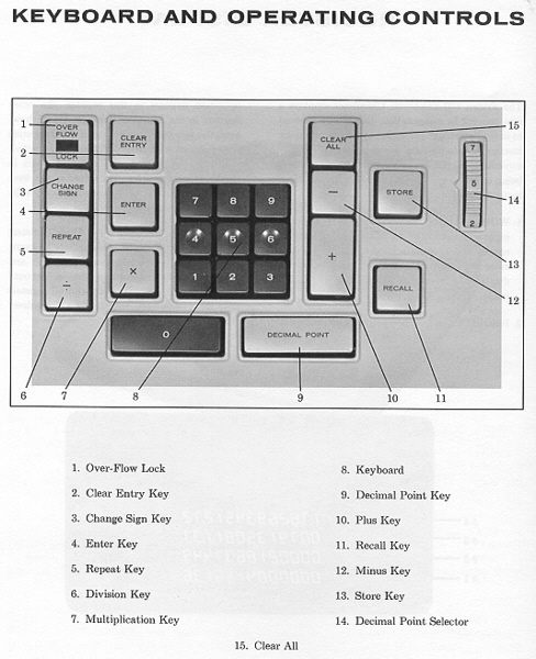


Image Courtesy Sergei Frolov

Sincere thanks to Alex Floca for providing these images.
Thanks to Alex Floca for supplying this photo.