
| +Home | Museum | Wanted | Specs | Previous | Next |

Victor Series 1400 Model 322 Electronic Calculator
Updated 3/8/2023
The Victor 1400 series of calculators (which included two machines, the 14-321, and the 14-322) were Victor's second attempt at marketing fully-electronic calculators of their own design. Victor's first attempt ended up a bit of a disaster that damaged the company's market reputation for a few years during the heyday of the emergence of electronic calculators. The difficulties (and cost) of developing the calculator spooked Victor Comptometer's management as far as electronic calculators were concerned. This story is worthy of telling, and provides a great lead-in for the exhibit on the Victor 14-322.
In October of 1965, Victor Comptometer, a company well-respected in the mechanical calculating machine marketplace, leapfrogged the state of the art by announcing a completely solid-state electronic calculator made of large scale integration (LSI) MOS (Metal Oxide Semiconductor) integrated circuits. The machine, designated the Victor 3900, was hailed by trade publications as a miracle of modern technology -- a completely solid-state electronic calculator at a time when the few electronic machines that were in existence utilized discrete transistorized electronics and holdover memory technology from the 1950's, including magnetostrictive delay lines, magnetic core memory elements, or magnetic drums.

The Victor 3900
The story of the Victor 3900 begins in sometime in the 1961 to 1963 time frame, when management of Victor Comptometer realized that electronics were extremely likely to have an impact on the calculating machine marketplace. Sumlock Comptometer/Bell Punch had their cold-cathode Thyratron tube-based electronic calculator (see the exhibit on the Anita C/VIII (Mark 8)) on the market in 1962, and was doing a brisk business, even though the technology in the machines was quickly becoming outdated due to transistor technology. Victor's management was concerned that the rapid advance of electronics was going to place their core business in mechanical and electro-mechanical calculating machines at risk. As a result or this concern, Victor's management implemented a strategic plan stating that the company would aggressively develop their own electronic calculator that would take definitive control of the marketplace through the use of advanced electronic technology.
Victor had earlier made acquisitions that provided electronic design expertise to the company. They also aggressively hired electronic engineers and technicians to rapidly put in place the expertise needed to succeed with a fast-track, high-technology project. The project was to develop an all-electronic calculator. By early 1963, Victor had developed a prototype of an electronic calculator, but the technology and form-factor weren't quite ready for production. In fact, the prototype machine filled a room with electronics racks, and was built using tube technology -- but it did work, and provided the basic logic design and features that Victor wanted in the electronic calculator that they intended to bring to market.

The problem that Victor had was that they really didn't have the resources to turn this huge prototype into something that would fit on a desktop. Victor found the answer in a March, 1963 edition of "Electronic News", a periodical devoted to the electronics industry. A short article told of a prototype desktop four-function, eight digit electronic calculator developed by Howard Bogert, an engineer at the fledgeling integrated circuit manufacturer General Micro-electronics (GM-e), a recent spin-off of semiconductor pioneer, Fairchild.
GM-e's founders left Fairchild to found the company in 1963 because they (correctly) felt that MOS (Metal Oxide Semiconductor) integrated circuits were the key to developing large scale integration, where hundreds of transistors could be placed on a single chip. At the time, Fairchild's management was focusing on its profitable bipolar small-scale logic IC lines. As a result, no traction could be gained within Fairchild to develop MOS technology. GM-e quickly got off the ground working on lucrative but highly secret IC development work for the U.S. National Security Agency (NSA). GM-e developed specialized ICs using bipolar technology that was used in government and military encryption and decryption systems. This work provided capital to allow the company to build up the necessary resources to develop its MOS integrated circuit processes.
The calculator Bogert had developed used GM-e's small-scale integrated circuit devices. It seemed to Victor's management that perhaps GM-e just might have what it takes to turn their calculator design into a production reality using bleeding-edge integrated circuit technology.
Victor contacted GM-e, negotiations progressed, and in October of 1963 a contract was signed between GM-e and Victor. The terms of the contract stated GM-e would design and build a calculator to the specifications provided by Victor (based on the logic design of the vacuum-tube prototype that Victor had built), using GM-e's MOS (Metal Oxide Semiconductor) Large Scale Integration technology. Victor would pay GM-e $50,000 a month to help fund the development work. The contract would provide a $500,000 bonus in April of 1964 if 25 production calculators were delivered by this time. This was an extremely aggressive, but would pay off nicely for GM-e if they could pull it off. The contract also stated that the production calculator would perform all operations in 400 milliseconds (4/10ths of a second) or less, would have twenty digit capacity, two memory registers, a CRT display, full floating decimal point, and be able perform all four basic math functions automatically. Victor had determined that the machine would be called the Victor 3900, as the address of Victor's headquarters in Chicago, IL, was 3900.

One of the GM-E made MOS IC's in the Victor 3900
Image Courtesy George Lemaster
GM-e promptly began the process of figuring out how to take the logic designs that Victor engineers had already created, and implement them on a small (for the time) number of large-scale MOS integrated circuits. Timing in the high-tech marketplace is everything, and the project to develop these revolutionary IC's was pushed along at a breakneck pace. In an amazingly short period of time, prototype chips were built, and even more amazingly, the chips worked straight-away, requiring no re-work, which, considering the complexity of the devices and the technology of the time, was an astounding accomplishment. The chip set making up the main logic of the calculator consisted of 23 unique fully-custom chips. Each chip was housed in a round ceramic package, in flat-pack configuration, with 22 gold leads. One of the chips was used seven times; a 100-bit general-purpose MOS shift register IC which were used as the working registers for the 3900 calculator. A total of 29 large-scale ICs made up the logic of the 3900. Just for comparison, the Victor 14-322 exhibited here uses 152 IC's, and does not have the capacity or the additional memory register of the 3900. This shows just how advanced the 3900 really was.
The first 25 production calculators were delivered to Victor on-time in April of 1964. The machines were designed and built entirely by GM-e - Victor's only role was to market and sell the machine as well as provide the service network for them. One board contained the integrated circuit main logic of the calculator. In early machines, this board consisted of a main logic board, with a small daughter-board containing the shift register ICs that plugged onto the main board, making two boards. Two other circuit boards, one containing what appears to be clock generation and timing circuitry, and the other containing the digit generation circuits for the display, were all combined together inside a plastic enclosure that protected the circuit boards, and allowed easy module-level replacement of the main electronics of the machine. In later 3900's, the daughter board was eliminated, and the shift register integrated circuits were bonded directly to the main circuit board. Four other smaller circuit boards in the machine include power supply filtering and regulation, high voltage supply, and CRT deflection amplifiers and blanking controls. It was a design that was way ahead of its time, and one that wouldn't be matched in the marketplace until Sharp unveiled it's 4-chip MOS/LSI-based QT-8D in late 1968, a full three years after the debut of the Victor 3900.

The main logic board from a fairly early-production Victor 3900
Note GM-e logo on circuit board, as well as numerous hand-soldered connections on some of the chips
Click on image for a more detailed view
Image Courtesy George Lemaster
At the time that these early MOS integrated circuits were developed, there were still many mysteries relating to the physics of such complex devices. One aspect of the architecture of MOS integrated circuitry is that it is inherently sensitive to electrostatic discharge (ESD). Though means were eventually invented to minimize the chance of damage to MOS devices by ESD, the early MOS chips created by GM-e didn't have the benefits of such protection, and could easily be damaged just by handling. Even today, special handling procedures are recommended for integrated circuits, as they still remain sensitive to ESD. In these early chips, with hundreds of MOS transistors per chip, the chances of a stray static discharge damaging a transistor (thus rendering the chip defective) were quite high. As a result of this sensitivity, the IC's were rather temperamental. It turned out that electrostatic discharge through the user touching the keyboard of the calculator was powerful enough to work its way into the MOS integrated circuits and cause damage. As a result, some early 3900's ended up failing in the field. Unfortunately, repairing the circuit board was a major challenge, as repair operations tended to create electrostatic discharge that could cause even more damage. To complicate repair, the chips were bonded to the circuit board using a special thermal welding technique, making it difficult for service technicians to replace the ICs in the field. GM-e worked furtively to come up with a solution to the problem. In time, a solution was found, which involved a modification to the circuit board to include protection circuitry for the sensitive inputs of the integrated circuits.
However, other forces were afoot while all of this was going on. GM-e had expended a tremendous amount of money developing the technology necessary to create the Victor 3900, and was in financial crisis. Philco-Ford purchased the troubled company in 1966, and for a period of time, IC's in the Victor 3900 were marked as being manufactured by Philco-Ford. In 1968, Philco-Ford management decided that it should consolidate its operations, and move GM-e from its Santa Clara facility, to Pennsylvania. This move effectively killed GM-e, as most all of the highly knowledgeable engineers had no intention of moving away from California and left the company en-masse.
While many of the Victor 3900's worked well and was well-received by those who purchased it, the problems with ESD-related field failures, and servicing issues, combined with GM-e's financial difficulties, caused Victor to withdraw the 3900 from the market, with approximately 2000 machines having been produced. The sad reality was that Victor's aggressive charge to dominate the electronic calculator market simply pushed the boundaries of the state of the art just a little bit too far.
By 1968, there was nothing left of GM-e, other than its historic legacy of having produced the first all-solid state integrated circuit calculator chip set. Some groups of ex-GM-e engineers and businessmen banded together with other semiconductor industry movers and shakers and formed Electronic Arrays, a company that developed some early LSI calculator chip sets, along with MOS memory chips (ROM & RAM) that ended up being used by numerous manufacturers of electronic calculators in the early 1970's. Some of EA's customers included Cintra, Wang Laboratories, MITS, ICM, and Master Calculator Co. While GM-e was gone, many of the ideas that the company strived to accomplish came to reality again within Electronic Arrays. Another notable IC company that rose from the ashes of GM-e was American Micro-systems, Inc. (AMI) (now known as AMI Semiconductor), which ended up being the market leader and major innovator in MOS/LSI circuitry for a very long time, and is still a strong player to this day.

Victor 14-322 with top cover removed.
The difficulties with the 3900 caused Victor's management to be sensitive about venturing further into the electronic calculator market on its own. After the withdrawal of the 3900 from the market, Victor contracted with the German company Nixdorf, which had purchased a small East-German company called Wanderer Werke. In late 1964, Wanderer Werke had introduced an all-electronic transistorized printing calculator called the Conti. The Conti is claimed to be the first electronic printing calculator, which isn't quite true, as it was preceded by the Mathatronics Mathatron. However, the Conti was the first electronic calculator to print on standard adding-machine tape. Victor re-badged the Wanderer Conti as the Victor 1500, and returned to the electronic calculator market with this machine sometime in late 1967 to early 1968. Victor's long history of producing fine quality mechanical adders and calculators in conjunction with it's proxy entry into the electronic calculator market via the Wanderer calculator allowed the company to recover from the business difficulties of the 3900, even though successful electronic calculators from Friden, Wang, and numerous others had definitely shown that electronic calculators were well on the way to taking the market from mechanical calculating machines.

Tag on bottom of machine indicating the machine's delivery date
Finally, after retrenching for nearly two years, Victor ventured back into making its own electronic calculator with its 1400-series calculators. These machines were of a much more conservative design than the 3900, utilizing a family of tried and true DTL (Diode-Transistor Logic) small-scale bipolar integrated circuit logic developed by Fairchild. The development of the 1400-series began in early 1968, and both machines were introduced in early 1969, a rather fast development cycle. The machines met with a fair degree of success in the marketplace, in spite of Victor's earlier problems. The particular 14-322 exhibited here was manufactured in early 1970, based on date codes on various components in the machine, and has a tag on the bottom indicating that the machine was delivered to its original purchaser on June 19, 1970.
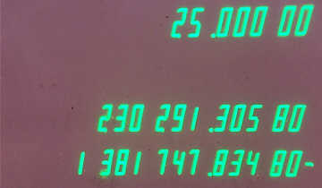
CRT-Display of the Victor 14-322 in operation
There were two different models in the 1400-series, though both machines shared many characteristics. The two models in the line were the Model 322 (as exhibited here), and the Model 321. Both models utilize a CRT display tube (a 5" RCA 4499 tube with Green P1 Phosphor) for presenting output to the user, showing the content of three registers with digits drawn in a slightly modified version of the familiar seven-segment form. The modifications include adding a 'tail' to the top segment of the "7", and slightly reducing the height of the "1", which also affects the "4". The display provides leading zero suppression, and automatically groups displayed numbers into three digit blocks for easier reading. Both machines provide addition, subtraction, multiplication, and division, and have a capacity of 14 digits.

A 412µS Magnetostrictive Delay Line, manufactured by
Andersen Laboratories, Inc.,
serves as the main memory for many of the Victor 14-322 and some
Victor 14-321 calculators
Note Date Code of 6940, 1st Week of October, 1969
The electronic architecture of the machine is quite conventional, based on a bit-serial arithmetic unit, with a 412 microsecond magnetostrictive delay line (manufactured under contract to Victor by Andersen Laboratories, Inc., Bloomfield, Connecticut) operating at 1MHz, serving as a shift register that circulates the content of the working registers through the arithmetic and display subsystems. A later revision (implemented sometime in 1969) of the 1400-series calculators replaced the delay line with two large-scale 200-bit MOS shift register integrated circuits. Why the change from the delay line to IC shift registers was made is unclear. It could also be that the delay line technology used may been somewhat expensive, with the use of IC memory allowing a cost reduction which could be passed on to the customer. Whatever the reason, the switch to solid-state memory added only a little additional lifetime to the 1400-Series. In reality, the machine was actually outdated before it was introduced. CRT displays were expensive, and could be temperamental compared to Nixie tubes, and the new up-and-coming Vacuum-Fluorescent display technology. IC technology was also advancing very quickly, which made it possible to dramatically shrink the size and cost of a full-featured calculator. According to old Victor documentation, both models were declared obsolete on January, 20 1971. Production of the machines likely ceased shortly after that date, with sales continuing until inventory was depleted. Overall, the 1400-series was likely produced for just under two years. In early 1971, the retail price quoted for a 14-322 was $995, which, by educated guess, would mean that it sold for something in the neighborhood of $1,295 at introduction.

Top view of 14-322 chassis
The machines are designed around a somewhat unusual arithmetic register architecture. First, there is an entry/result register, into which numeric entry occurs and final results of math operations are placed (displayed on the bottom line of the CRT display). Next is a multiplicand/dividend register which holds the first number of multiplication and division problems (shown on the middle line of the display), automatically serving as a constant for multiplication and division. There is a non-displayed temporary register used in addition and subtraction operations. Lastly, are the memory register(s). The content of the accumulating memory register is displayed on the top line of the display. All of the working registers are capable of holding 16 digits, but two of the digit positions are used for housekeeping purposes, such as keeping track of the sign of the number in the register, along with storing the decimal point location.
Both the 14-321 and 14-322 provide a single accumulator-style memory register, while the 14-322 adds a second store/recall register, useful for holding temporary results during complex calculations. Both machines in the 1400-series provide a thumb wheel switch for setting the fixed decimal point location. Settings for 0, 4 or 6 digits behind the decimal are provided on the 14-321, and the Model 14-322 provides settings for 0, 2, 4, 5, 6, 8, 10 or 12 digits behind the decimal point.

The main logic board for the Victor 14-322
Both of the machines in the 1400-series contain has three main circuit boards. A very large (18"x13") circuit board occupies the entire bottom of the chassis. This single board contains all of the digital logic of the machine. In the Model 14-322, it is populated with 152 small-scale DTL devices made primarily by Fairchild, but with the few Texas Instruments parts sprinkled about. The devices are all in 14-pin dual-inline plastic packages. Unfortunately, Victor saw fit to have the IC manufacturers place Victor-specific part numbers on all of the IC's (e.g., 50210-x), so it's a bit of a challenge to figure out exactly what function of each particular part number provides, however, my guess is that the devices are from Fairchild's popular DTµL line (with the TI parts being functional equivalents) of bipolar integrated circuits.

Closer view of IC's used in Victor 14-322
Note mix of Fairchild & Texas Instruments parts
Two groups of square pin connectors on the main logic board provide the connections to the rest of the machine. One connector hooks up to the keyboard assembly, and the other connector provides power supply, connections for the recirculating memory, and logic signals that direct the operation of the CRT display. A second board, approximately 11"x4", oriented vertically on the left side of the chassis, contains discrete components, with one single linear integrated circuit. This board creates the low voltage power supplies (for the logic and deflection amplifiers for the CRT); provides Digital to Analog Converters that are used to generate the vectors that draw the numerals on the CRT display; the CRT deflection amplifiers; and signal conditioning for the magnetostrictive delay-line memory (or in later models, the two MOS shift register IC's which replaced the delay line).
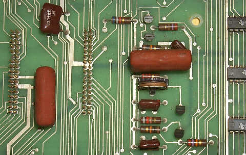
The discrete components on the main logic board, including clocking and keyboard de-bounce circuitry
Note square pins for keyboard & display connections
The third circuit board, oriented vertically on the right side of the CRT provides the high voltage power supply (Approximately. 2200 Volts DC) needed for generating the electron beam in the CRT, as well as providing for focus and brightness controls. The power supply of the machine is a traditional linear supply, with a rather large multi-tap transformer, feeding standard rectification and electrolytic capacitor filtering. Most of the supply voltages (+5V logic supply, +12V, -6.2V, and -24V) are zener diode/pass-transistor regulated. A low-current +136V supply is zener regulated, and an unregulated 6.3V AC winding in the transformer is used to power the heater element in the CRT.

A close-up of a key switch module from a Victor 1400-Series calculator
The keyboard in both machines utilizes very high-quality modular key switch units, with two sets of dual gold plated contacts for reliability and minimization of contact bounce. Even so, there is a special timer circuit in the machine that delays the sampling of key closures by a few milliseconds to allow any contact bounce to settle out. The surprising part about these keyboard switches is that they are an open-frame switch, with the contacts exposed to the environment inside the cabinet. This makes them susceptible to dust and atmospheric contaminants that could potentially cause problems with reliable key switch operation, but even after 30-plus years of service without any cleaning, the keyboard in the 14-322 exhibited here works very smoothly, with no glitches. The key caps are made of plastic, with molded in color and nomenclature. The power switch is made up of a slide switch located at the left of the keyboard panel.
The machine is built upon an aluminum chassis that is quite nicely made, and very study. The circuit boards are mounted to the chassis with machine screws that hold them in place. The wiring harness consists mainly of individual wires that interconnect the circuit boards, using hard-wired connections, or plug-type connections. The cabinet is made of plastic, with two parts, a base, and the upper cabinet. The upper cabinet is made of a few parts, including the main cabinet section, and two pieces that form the "bubble" that makes up the hood and viewing screen for the display. The base part of the cabinet is colored a forest green color, and the upper part an almost turquoise color. However, with age and exposure to atmospheric contaminants, the color of the upper cabinet oxidizes to a rather sick-looking brownish-green. The keyboard bezel is painted a medium-gray. Cooling is by convection only, with cooling grates in the base, and at the back of the upper cabinet to allow air to flow through the cabinet to cool the components. The machine does generate a sizable amount of heat, and the cabinet gets clearly warm to the touch after operating for 15 minutes or so.

Operator's controls for the Victor 14-322
Both the 14-321 and 14-322 operate conventionally, with arithmetic addition and subtraction, and algebraic multiplication and division. Addition/subtraction are performed by entering a number, followed by the [+] or [-] key, which immediately adds or subtracts the entered number from the amount in the hidden working register, then copies the working register in to the entry/result register. Multiplication and division are entered as they would be written, by entering the first number, pressing the [X] or [÷] key, which moves the entered number into the multiplicand/dividend register, entering the second number, and pressing the [=] key, which calculates the product or quotient, and places the result in the entry/result register, leaving the multiplicand/dividend register untouched, allowing for easy multiplication and division by a constant. Two clearance keys are provide, [C], which clears the entry/result register (used mainly for correcting entry errors), and the [C ALL] key, which clears all of the working registers, along with the accumulating memory register. Specifically on the 14-322, a number of keys control the operation of the two memory registers. The [M IN] and [M OUT] keys control the operation of the store/recall memory. Pressing the [M IN] key copies the current content of the entry/result register into memory. The content of this storage register is not displayed on the CRT. Pressing the [M OUT] key recalls the content of the register to the entry/result register, destroying the previous content of the entry/result register. The content of the store/ recall register remains until modified by operating the [M IN] key. The other memory register in the 14-322 is a full accumulator-style memory register, capable of accumulating sums and differences. This memory register is displayed on the top line of the CRT display at all times. A total of four keyboard keys control the operation of this register. The [=+] key carries out two operations. It first finishes multiplication or division operation in progress (placing the result in the entry/result register), and then adds the content of the result register to the memory register. The [=-] key performs the same function, but subtracts the result from the memory register. The [S] and [T] (for Subtotal and Total) keys provide a means to utilize the number in the accumulator memory. Pressing the [S] key copies the content of the accumulator memory into the entry/result register, destroying the previous content of the entry/result register. The accumulator memory is left untouched. The [T] key performs the same function, but clears the accumulator memory after the transfer occurs. Lastly, the large [STORE] key, a push-on/push-off mode key. When this key is in the depressed position, it cause the calculator to add or subtract the number in the entry/result register to/from the accumulator memory upon depression of the [+] or [-] key. This feature is useful for accumulating grand totals of sequences of addition and subtraction operations.

Overflow indication on CRT display of the 14-322
The 1400-series machines have very few quirks, clearly a result of careful logic design. The machine is very good at detecting error conditions, such as calculation overflow, entry overflow, and division by zero. The full 14-digit capacity of the machine is available for all operations. When an overflow/error condition occurs, the machine displays all digit positions filled with a rather odd character that consists of all segments (including segments normally blanked) on at once, and inhibits operation of all keyboard keys except the [C] and [C ALL] keys. Pressing the [C] key will clear the overflow condition, restoring the display to normal, with the memory and multiplicand/dividend registers as they were before the error condition, and the entry/result register cleared. Pressing the [C ALL] key clears the error condition, as well all working registers, and the accumulating memory register. If an overflow is caused by the accumulating memory register exceeding capacity, unusual results can be left in the register if the [C] key is used to clear the overflow condition. The machine does not have a power-on reset circuit for the registers, so typically when the machine is turned on, it comes up in overflow state, requiring a press of the [C ALL] key to clear things before calculations can begin. However, there is one slight flaw with this. The Store/Recall memory register isn't cleared by the [C ALL] key. So, after powering up and performing [C ALL], then pressing the [M OUT] key can result in strange content being recalled into the Entry/Display register, sometimes resulting in an immediate overflow condition, or sometimes resulting in an invalid bit sequence which can result in odd behavior of the display system. To properly clear the machine after power up, the key sequence should be [C ALL], followed by [M IN], to clear the Store/Recall memory register.
The machine utilizes a master clock frequency of approximately 2MHz. This master clock is divided in half to generate the main timing signal of 1MHz, which is used to clock data through the delay line. This 1MHz signal is further divided down into sixteen operational time-slices that step the machine through its various states. As a result, the machine is quite fast. Addition and subtraction occur with no apparent delay. Multiplication and division are also quite quick, but a slight flicker of the display is noted for all but the most complex operations. During calculation, the display is blanked, so on more complex multiplication and division operations, there is a quick, but noticeable dropout in the display. The Old Calculator Web Museum benchmark calculation of all 9's (in this case, 14 9's) divided by 1 completes in approximately 1/3rd of a second. Multiplication of 9,999,999 by itself takes a little over 1/4 second. Both calculations yield the correct result.