
| +Home | Museum | Wanted | Specs | Previous | Next |
Commodore 500E Calculator
Updated 2/16/2026
The Commodore 500E is an interesting lead-in to the story of how Commodore got into the electronic calculator business. It all started when Jack Tramiel founded Commodore in 1954, as a typewriter service company. As time went on, the company licensed the design of a Czechoslovakian-made typewriter and began manufacturing the typewriters for sale under the Commodore brand. Intense competition in the typewriter market led Tramiel to come to the conclusion that in order to survive, his business would have to diversify. In the early 1960's, Commodore began manufacturing low-cost mechanical adding machines, again under license from foreign manufacturer. As with the typewriters, competition in the low-cost adder market led Tramiel to yet again search for the next "big thing" in business machines to keep his company moving forward. That step led him to Casio Computer Co. in Japan.
In 1957, Casio Computer Co. was founded to develop a relay-based electrical calculator. Casio's founders believed that relay technology held the key to building calculating machines that were vastly superior in speed and capability to the mechanical machines of the time. In June of that year, Casio introduced its first machine, the 14-A after some struggles with reliability that led to difficulties receiving funding to go into production of the calculator. Once the financial hurdles were cleared and the machine went into volume production, the 14-A demonstrated that relay-based calculators were not only practical, but also very reliable and much faster than mechanical calculators. Casio continued to develop its relay calculators, creating ever-more capable machines, including mechanically programmable calculators that blurred the line between calculator and small computer. However, relays were not the wave of the future. In 1961, Sumlock Comptometer in England had developed an all-electronic desktop calculator (the ANITA Mk7/Mk8) using cold-cathode (unlike vacuum tubes which used a hot cathode that was kept hot by a heating element inside the tube.) Thyratron tubes, demonstrating that desktop electronic calculators were where the market was going to move. By 1963, many companies were working on development of transistorized electronic calculators, and in 1964, the market exploded, with entries from Sharp(then Hayakawa Electric), Friden, IME, Canon, Mathatronics, Wyle Laboratories, and more Thyratron-based calculators from Sumlock. Casio was caught off-guard by the development of purely electronic calculators, getting a late start on their own electronic calculator development. It took until the fall of 1965 before it introduced its own transistorized desktop calculator, the Casio 001.
Casio met with good success selling the 001 and its follow-on machine, the √001 (which provided automatic square root), in the Japanese market, although these machines had some reliability problems that led Casio management to worry that selling them outside of the homeland could become a service nightmare.
The problem with reliability was that Japanese transistor manufacturers were making transistors based on the semiconductor Germanium. Germanium was the first material used in transistors, as physicists and electronic engineers had come to a solid understanding of the physics of its semiconductor characteristics because Germanium was heavily used to create solid-state diodes as a replacement for troublesome Selenium diodes. Selenium was initially used for first mass-marketed solid-state diodes, but it had a lot of long-term reliability problems. Diodes are an electronic component that lets electricity flow mostly unimpeded in one direction, but resists the flow of electricity in the other direction. Diodes are a critical electronic component used in everything from radios and TVs to computers and communications equipment, not to mention, early (pre-integrated circuit) electronic calculators, which typically have many hundreds of them scattered about the circuit boards. The typical use of diodes in electronic calculator circuitry is for creating logic gates, which when connected together create the logic that orchestrates the operation of the calculator. While Germanium worked reasonably well for diodes, whose electrical characteristics did not have to be as carefully controlled as in a transistor. one weakness that Germanium had is that its semiconductor characteristics would go wonky if the Germanium was exposed to even miniscule levels of humidity. This meant that Germanium diodes had to be manufactured in a very controlled environment, with the tiny slab of Germanium sealed inside a tiny glass tube, with the two wire leads of the diode protruding through the glass at each end of the tube, with melted glass creating the seal to keep ambient moisture away from the Germanium.
Transistors were a bit more complicated to manufacture than diodes because they required three leads(called the Emitter, Collector, and Base). Making a glass envelope to enclose a device with three leads proved to be rather difficult, way too fragile, and also somewhat expensive. Instead, a pressed lightweight thin-walled metal alloy tube, capped at one end, with the other end open, formed the housing. The tiny Germanium transistor chip with its connecting wires was carefully lowered into the housing such that no part of the transistor touched the housing, with the three leads protruding out the open end of the housing. Once the guts of the transistor were properly positioned, an electro-chemically inert substance was poured into the housing to fill it. This material would fairly quickly harden, sometimes exposed to low heat, or ultraviolet light to accelerate the hardening, The material, once hardened, created a seal across the open end of the housing and around the devices leads, isolating the Germanium chip from the outside world. The three metal lead wires of the transistor (which were made of solid Gold on early transistors or specialized transistors used in computer and aerospace applications) were commonly made of a small-gauge metal alloy wire that had low electrical resistance, was resistant to corrosion, was flexible enough to be able to be formed to fit into holes on a circuit board or socket, yet sturdy enough to withstand the forming/bending without breaking or causing electrical connection faults, and would be easy to solder to. The leads extended through the filler material and out of the package an inch or two to provide the electrical connections to the transistor.
Like Germanium diodes, Germanium transistors had to be manufactured under very tightly-controlled environmental conditions. The Japanese semiconductor manufacturers had been making Germanium diodes in production quantities for quite some time, developing their own processes for creating and maintaining the proper environment for the large-scale fabrication of Germanium diodes. In many cases, Japanese ingenuity was applied to the manufacturing processes resulting in very efficient production facilities that produced high-quality, stable and reliable diodes. In fact, the Japanese got so good at manufacturing Germanium diodes that American and European electronics companies began buying their diodes from Japanese manufacturers.
Japanese companies had to license transistor technology from US semiconductor companies such as Texas Instruments(TI), Motorola, Radio Corporation of America(RCA), General Electric(GE), and Raytheon (among others), all of whom had originally licensed the technology from the organization responsible for the invention of the transistor, Bell Laboratories. The Japanese transistor licensees paid a fee to the US company they purchased their license from, which granted them access to design information for the transistor manufacturing technology utilized by the licensor. The licensees were provided of the information concerning the processing of the Germanium, along with methods for controlling the electrical characteristics of the transistor by "doping" the Germanium with impurities such as Arsenic, that would alter its electrical characteristics to suit the needs of a particular transistor application. Information was also provided concerning how to positively bond wire leads to the connection points on the transistor chip. These are just a few examples of some of the details that the Japanese transistor licensees would receive in return for paying the licensing fee. Along with the licensing fee, there was a royalty fee that was also paid to the US manufacturers for each transistor that was manufactured (including faulty units or units that did not sell).
This information gave the Japanese everything they needed to create transistors in the laboratory that would operate under closely-controlled conditions. What was missing was detailed information on how to package the transistors so they could stand up to the rigors of the applications in which they were to be used. There were generalities about the various packaging methods that had been developed by US transistor manufacturers, but the provided information was seriously lacking in details, specifically the types of materials that were used to package the transistors, and what packaging methods and processes worked, and which didn't work so well..
While Vacuum Tubes had been ruggedized so that they could survive the stresses of being launched on a rocket or surviving the frigid conditions experienced by a satellite in deep space, the methods necessary to keep the tubes operating properly were expensive and difficult to implement. The huge promise of transistors was that they would be much more physically robust than vacuum tubes, require far less power to operate, generate orders of magnitude less heat, could operate at speeds considerably faster than vacuum tubes, were much less expensive to manufacture in quantity than vacuum tubes, and took up far less physical space. Every one of these benefits of the transistor made the designers of electronic calculators dream of the amazing machines they would be able to produce, if only they had the transistors they needed. An electronic calculator didn't necessarily need to meet the stringent requirements of spacecraft electronics, or operate at the speeds of large mainframe computers. the key benefits of the transistor for use in electronic calculators was the small size, low power requirement, much less heat generation, and high reliability.
It was up to the Japanese manufacturers to figure out how to package their transistors. It was pretty obvious from observing US-made transistors how they were packaged, but the material that was used to fill the package to isolate the Germanium from the outside environment was a mystery. The Japanese had to adopt a trial-and-error means to develop their own sealant material that would properly protect the Germanium inside the package, isolating it from the package, being electrically inert, protecting the transistor from impact forces and vibration (as in space and aerospace environments), insulating the chip from heat and cold, yet still allowing the tiny amounts of heat generated by the transistor to be conducted to the metal package where it could be radiated into the air, and most importantly, keeping water molecules from getting to the Germanium. A number of different materials were tried, with intensive testing that simulated accelerated long-term exposure to various operating conditions that the transistors could be exposed to, including high heat to extreme cold, high humidity to bone-dry atmosphere, and high vibration/shock environments. Many of the sealant materials would fail in one way or another, meaning that the designers would have to go back to the drawing board. Each of the Japanese transistor licensees developed their own solution to the packaging problems, all eventually a finding a material that seemed to stand up to all of the issues. Once that hurdle was crossed, the Japanese manufacturers very quickly ramped up production of transistors, with Hitachi, Toshiba, Nippon Electric (NEC), As it turned out, this method worked pretty well...for a while. There turned out to be microscopic voids in the filler substance that, over time, would allow molecules of ambient atmosphere to leak into the transistor and make it to the Germanium chip. Any molecules of water that happened to get in would cause the characteristics of the Germanium to change fairly radically, resulting in a transistor that would no longer perform as it was specified. This would cause a calculator made with such transistors to malfunction, leading to service calls, and difficult and time-consuming troubleshooting to repair the machines.
The Americans had figured out different sealant mixtures, cases, and manufacturing processes and environments that minimized this condition, which made their Germanium transistors considerably more resilient, allowing for calculators built with American-made Germanium transistors to still be fully function over a half a century later, as exemplified by Wang Laboratories and Friden Calculating Machine Co. early electronic calculators that still run just fine today. It is a rarity to find a Japanese-made electronic calculator from the mid-1960s that is still operational with all of its original transistors intact today. Fortunately, there are semiconductor manufacturers who still manufacture small batches of Germanium transistors to support a repair industry for vintage transistor radios, televisions, audiophile equipment, and even for certain types of military and crypto equipment that is still in service today.
American physicists and electrical engineers had discovered that Silicon, a major constituent of common beach sand, is a considerably more stable semiconductor than Germanium, and had begun manufacturing transistors based on tiny chips of very pure Silicon instead of Germanium. These devices were rather more complex to design, as there were myriad factors that contributed to the electrical characteristics of the transistor. While this was indeed a difficulty with early Silicon transistor manufacturing, processes were quickly developed that allowed consistent manufacturing batches of transistors with operating parameters that were very close to each other.r Silicon transistors were more power-efficient, much more stable and resistant to contamination, could switch considerably faster than Germanium transistors, and most importantly, once manufacturing volume increased, were less expensive to make, because Germanium is a rare-earth element, while Silicon is everywhere. It took time for the US transistor manufacturers to build out new production lines for Silicon transistors, partly because they had to keep making their lines of Germanium transistors for all kinds of things from transistor Radios to computers and military electronics that used them. It also took time before Japanese semiconductor companies could license the manufacture of Silicon transistors from the American companies. As a result, there was a period of time where the Japanese calculator manufacturers would either have to buy ready-made Silicon transistors from America (a somewhat expensive proposition), or just keep using their home-grown Germanium transistors.
It was impractical from a cost perspective for Casio to buy transistors from US manufacturers, so they had to wait until their homeland manufacturers (primarily Hitachi and Toshiba) could produce reliable Silicon transistors at a reasonable price. Once that happened, Casio was ready with a new design for a calculator that would use domestically-produced Silicon transistors. With the reliability that Silicon transistors provided, Casio would be able to offer its calculators to the world with the knowledge that their machines would be much more reliable than their earlier calculators. With exporting the 101 in mind, Casio embarked on building out the infrastructure to support a world-wide distribution and service network, with a major focus on the very lucrative North American market.
The new Casio 101 was introduced in Japan in July of 1966. The
101 was designed to address the international market, with modifications to power supply
circuits to be able to run on the varying power grids of countries outside of Japan, which
has an unusual 100 Volt AC power grid, along with other design changes to reduce cost and
increase serviceability. The 101 was purposefully designed to be the machine
that Casio would offer up to distributors for export. In September of '66, a deal was struck with Remington, who had a large distribution network of office
machine retailers in Australia. The agreement provided for Casio to supply
Casio 101 calculators to Remington, and they would sell and service
the machines through
their network in Australia under the Remington badge. The Casio badge on
the front of the machine was replaced with a Remington badge, but the model/serial number tag on the back still shows Casio.
The Casio 101E
At around the same time, Casio introduced a somewhat modified version of the Casio 101 called the
Casio 101E. This machine dispensed with
the row of rotary switches on the front of the 101 that provided a way to set a
seven digit constant value, a feature that carried over from Casio's
relay calculators, and proved not to be that useful. Removing the eight rotary switches, associated
mounting hardware, and circuitry associated with them resulted in a tangible cost savings that translated
to a lower price for the consumer - a critical selection parameter in the hugely competitive electronic
calculator marketplace that had emerged in the mid-1960's.
Success of the Australian distribution and service agreement with Remington gave Casio the confidence that
their machines were ready for the world market, and in March of '67, an official
deal was inked between Casio and Commodore for Commodore to market Casio's machines under
the Commodore badge, with Commodore's established presence in North America
performing all of the marketing, sales, distribution and service.
It appears, although not verified at this writing, that Commodore did not market the Casio 101
as part of the deal with Casio. Instead, the first
electronic calculator that would be sold by Commodore
was the Casio 101E, which was sold by Commodore as the Commodore 500E.
In order to maintain a degree of brand differentiation between Casio's
machine and that sold by Commodore, the 500E has the addition of a rotary
switch to set the fixed decimal point location of the memory register.
Casio's 101E did not have this selector, with the memory register
decimal point location set based on the numbers entered into the memory
register.
This capability for a switch selectable fixed decimal point location for
the memory appears to have been designed into the 101E from the beginning,
with differing wiring in the backplane selecting the way the machine operates.
The rotary switch has twelve positions, with ten of the positions used.
Settings are provided for setting the memory decimal point location from zero
through nine digits behind the decimal point. The two unused switch positions
select zero digits behind the decimal. Also, there are slight differences in
the cabinetry between Casio's machines and Commodore's machines. These
changes were likely made to Commodore's machines to provide some brand
differentiation. It is interesting to note that this machine is very similar
in appearance to a somewhat later-design Casio/Commodore machine in the museum,
the Commodore AL-1000. The
upper and lower parts of the cabinet, as well as mechanical construction between
the two machines is very similar. It is also notable that the Casio version
of the AL-1000 (also called the AL-1000) uses the exact same cabinet design
as the Commodore version of the machine, perhaps providing an indication that
Casio updated its cabinet design to match up with the more modern styling
used by Commodore with the 500E. In most OEM situations, the customer could opt
to provide their own cabinetry for the electronics, in order to provide another
means to uniquely identify the final product, and perhaps Commodore developed
their own cabinet design for the 500E, and Casio liked it so much that they
got permission from Commodore to use that cabinet design for the upcoming AL-1000.
This is all just supposition, but it seems a decent probability.
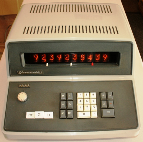
The Nixie Tube Display
The 500E has ten digits of display, indicated by ten large
side-view Nixie tubes. The tubes are made by NEC (Nippon Electric Company), and are type CD-66 tubes.
The CD-66 tube was used in quite a number of Japanese-made calculators,
including machines of similar time-frame made by
Sharp (the Compet 20)
and
Toshiba (the Toshiba BC-1411).
The display is very easy on the eyes, with large 5/8-inch tall digits. Each Nixie tube
contains the digits zero through nine and a right-hand decimal point. The Nixie tubes are
retained in a rubber cradle that holds the tubes in place and provides some shock isolation
for the delicate tubes. Each Nixie is driven by its
own display decoder/driver circuit, which takes a 4-bit Binary-Coded Decimal
(BCD) digit, and converts it to a 1-of-10 signal that turns on a driver
transistor, and allows
current to flow to the selected digit. For example, if the 4-bit code
is 0101 (Binary-Coded Decimal for 5), the digit 5 would
light up in the tube. This individual per-digit decoding/drive circuitry
consumed over 100 transistors just by itself. This driver-per-digit design
was common on early electronic calculators from
many manufacturers, but, while simple, required a lot of components, and
thus was costly. This component-heavy display technology was soon replaced by a
concept called multiplexing, whereby there was one decoder circuit, and
each Nixie tube was lit for a short period of time, sequentially, sharing
the decoder/driver circuit amongst all of the digits in the display.
This would result in what appeared to the human eye as a continuous
display, because the digits were strobed quickly enough that the eye didn't
notice the scanning process. Multiplexing significantly reduced component
count and cost. The Casio 101E and Commodore 500E were
the last of Casio's electronic calculators to use the decoder/driver per-digit design.
Commodore 500E Keyboard Detail
The 500E uses three working registers, the display register, the
temporary register, and the memory register. Each working register consists
of ten groups of four flip-flops each. Each flip-flop can store a single
0 or 1. Each group of four flip-flops can store a binary-coded
decimal number ranging from 0 through 9 (along with 6 other undefined
states). With ten groups of four flip-flips (for a total of 40
flip-flops), a complete ten-digit number can be stored.
Each flip-flop uses two transistors, so the register storage
uses a total of 240 transistors just to hold the digits. Each of the
working registers consumes one full circuit board in the calculator.
Later calculators from Casio utilized small magnetic core memory elements
for register storage, dramatically reducing the component count.
Operation of the machine is
conventional for machines of the time, using arithmetic logic for addition
and subtraction, and algebraic logic for multiplication and division.
Addition and subtraction are done by entering a number to be added or
subtracted from the existing total, then pressing the large [=] key to
perform the addition, or the [=] key to subtract the number from the
running total in the display. Multiplication and division are performed by
entering the first number, pressing the [X] or [÷] key, then the
second number, followed by the large [=] key to calculate the result.
There are two keys for clearing the calculator;
one labeled [AC] which performs a master clear of
the machine (except for the memory register),
and the [KC] key, which clears the display only, allowing for correction of
incorrectly-entered numbers. Lastly, the [→] key shifts the
display one digit to the right, effectively deleting digits, to allow for
easier correction of a mis-entered digit. An unexpected aspect of this
function is that it will shift the decimal point off the right end of
the display, causing it to re-appear at the left end of the display.
The memory function provides an accumulator-style register, providing the ability
to store the content of the display in the memory register (using the [M]
key); to recall the memory register to the display, leaving the memory
register intact (via the [F] key); adding the number in the display to the
memory register (using the [+] key), and subtracting the number in the
display from the memory register using the [-] key. The only ways to clear
the memory register is to recall it to the display using the [F] key, then
pressing the [-] key to subtract this number from the memory register, or
clearing the display by pressing the [AC] or [KC] keys, then using the
[M] key to store zero into the memory register.
The hand-wired backplane of the 500E
The three white alternate action switches on the keyboard panel labeled
[PW], [Σ], and [FA] control the power, memory summation mode, and
display of an additional ten digits of products when multiplying. Pressing
the [PW] switch applies power to the machine, resulting in garbage in the
display for about 1/2 second, after which the machine's power-on clear
circuitry clears the display to "0000000000." The memory register is also
automatically cleared at power-on. The [Σ] key, when locked down,
enables the machine's automatic summation mode. Each time the large [=] key
is pressed to complete the calculation of multiplication or division, the
result of the operation is automatically added to the memory register,
resulting in a running sum of products or quotients accumulating in the
memory register. This mode is useful for calculations such as invoicing,
where a list of quantities of items, and item costs can be entered line at
a time to calculating total costs, with the memory register accumulating
the total cost of all of the items in the list. The [FA] switch
enables an additional ten digits of capacity when multiplying. When the [FA] switch
(which stands for Full Answer) is depressed, multiplication problems will automatically
store an additional ten digits of the product in the memory register, which can be recalled to the display
with the [F] key. This is useful for multiplication calculations that exceed the ten digit capacity
of the calculator. For example, performing 7912345679 X 72 with the [FA] key depressed will result in
upper-most ten digits of the product showing in the display, e.g., 5696888888 after the [=] key is pressed.
To show the final ten digits of the result in the display, pressing the [F] key will bring the content
of the memory register, which received the additional digits of the result of the calculation, to the display,
resulting in 88.00000000 being displayed, meaning the final result is 569,688,888,888. This feature is only
usable for multiplication, and does not provide useful results for addition, subtraction, or division.
Recalling the last ten digits of the multiplication operation obliterates the upper ten digits of the result,
so it's up to the user to copy them down on paper, then press the [F] key to retrieve the last ten digits.
Therefore, performing chain multiplication operations is not a useful operation using the double-precision
capability the [FA] key provides.
Unusual for its time, the Commodore 500E uses fully automatic floating decimal placement For all
math operations. The calculator will attempt to position the decimal point to provide the maximum possible
accuracy of the result. The decimal point position rotary switch on the keyboard panel does not affect
any results of normal calculations, but instead sets the fixed decimal point location for the calculator's
memory register. This allows, for example, setting the memory register decimal point location to '2',
and any operation that results in a number being stored into, added to, or subtracted from (via the [M],
[+], or [-] keys) being automatically rounded off to the decimal point setting on the selector switch, then
the operation is performed on the memory register. This feature is useful for accumulating grand totals of
amounts with a fixed number of digits behind the decimal point, for example, accumulating a grand total of
an invoice amount in dollars and cents.
Detail of the Nixie Display of the Commodore 500E in operation
The 500E does not have the capability of representing negative numbers. If a result is
less than zero, the tens complement of the result is displayed. In other
words, subtracting 1 from 0 results in "9999999999." This deficiency does
create some limitations when using the machine for financial functions, as
automatic credit balances aren't possible. The operator must be watchful
for cases where the machine "goes below zero".
Pressing the [=] key
will automatically convert a tens complement number to its normal
form. For example, performing 10 - 13 (by entering 10, followed by the
large [=] key, then entering 13, followed by
the [=] key will result
in the display showing "9999999997." Pressing the
[=] key at this point will result in
"0000000003." being shown in the display.
It is up to the user to keep track of the fact a negative result occurred.
As far as the electronics of the calculator go, the 500E is a very complex machine. The calculator
uses a total of nine plug-in circuit boards along with three other circuit boards. Each of the
nine plug-in boards are 12" wide by 7" tall in size, with most of the circuit boards packed full of
components. The display circuit
board that contains the Nixie tubes and their decoder/driver circuitry doesn't
plug in, but instead is connected by a large number of hand-soldered
ribbon cables to the
display register circuit board, resulting in a two board sandwich.
The keyboard connects
to another smaller circuit board that provides circuitry for conditioning the
signals from the keyboard switches.
All of the plug-in boards have edge-card connections
along the bottom edge of the circuit board. Some boards have two edge
connector locations, while others only have one. The boards plug in to a
hand-wired backplane that uses gold-plated edge connector sockets for reliability. The
circuit boards have components on one side of the board, and etched traces
on the other side. Jumper wires on the component side of the boards
provide additional connection paths when trace routing constraints on the
wiring side of the board require additional connections. Component lead
holes are not plated through. The circuit board material is copper-clad
phenolic. White silk-screen on the component side of the board provides
component value and type identification, as well as provides other
information such as signal names for assisting technicians
with troubleshooting, as well as board identification and other
information. Each board is packed
full of discrete components, with diode-resistor gating and transistors
for flip flops and other active logic elements.
The Model/Serial Tag on the Commodore 500E
The boards are numbered, front to back, from 1 through 9.
Designations on the boards indicate the internal Casio model designation
(in this case, 10B), followed by a dash, followed by the circuit board
number, followed by a space, and then the boards revision code (beginning
with A and progressing through the alphabet) inside a circle. The first board,
10B-1, contains the Display Register, and is plugged into the backplane
backwards from the rest of the boards, with the components facing toward the
rear of the calculator. This is because this board has myriad ribbon-cable
type wires connected to the back side of the board that run to the display
decoder/driver/Nixie tube circuit board. The remainder of the circuit boards
plug into the backplane with their components facing the front of the
calculator. The next three circuit boards area entitled "MAIN" (MAIN1:10B-2,
MAIN2:10B-3, and MAIN3:10B-4), which appear to contain the majority of the
state sequencing and control logic for the machine. Boards 5 and 6
(10B-5 and 10B-6) contain the temporary register and memory register flip-flop
arrays.
Boards 7, 8 and 9 contain what are called the "SUB" boards, SUB1:10B-7,
SUB2:10B-8, and SUB3:10B-9. These boards appear to be the
arithmetic unit of the calculator, where the logic to perform
basic addition and subtraction exist. Multiplication and division are
performed by repeated additions and subtractions orchestrated by logic
on the MAIN boards. The last board contains a fairly large (3" x 7") area
on the circuit board that is not populated by components. It is not known
what purpose this area of the circuit board performs when it is populated
with components, but clearly on this model of machine it is not intended
to be used, as there is a large red "X" marked in this area on the component
side of the circuit board.
Transistors in the machine are made by
Hitachi and Toshiba, and are all Silicon-based transistors. Transistor
types include 2SC641, 2SC371, and 2SC284(Nixie Drivers).
This particular 500E appears to have been
manufactured toward the later part of the first quarter of 1968, based
on date codes on some of the components.
Keyboard Construction Detail The keyboard design of the 500E
is unusual. Most every calculator of the time used magnetic
reed-switches for simplicity, reliability, and minimal contact bounce.
The 500E uses simple spring contacts for the keyboard, which is
quite surprising for such an otherwise robust
design. The key-caps press directly on one contact of the switch, making
a connection to a fixed contact, closing the circuit for the key.
This type of design would seem to be prone to problems as the contacts
age and suffer from free-air pollutants and moisture, however, the keyboard
has a very nice feel to it, and even though the machine is over 40 years
old, the keyboard operates fine, with no bounce at all, indicating that
the designers devoted a lot of effort to conditioning the signals from the
keyboard to minimize the possibility of wear and corrosion from causing
instability. Along with electronic protection, a plastic shield is secured
over the key-switch array, helping protect the switch contacts from environmental
contamination. The keyboard is hard-wired to a small circuit board that
contains 22 identical circuits which are used to condition the output from
each keyboard switch. This conditioning circuit board is also hard-wired
into the backplane of the machine, sending the various conditioned key-press
signals to the various boards where the signals are acted upon. It is
surprising that hard-wiring is used to connect the keyboard and keyboard
conditioning board into rest of the machine, as this would make the keyboard or
the keyboard conditioning board rather difficult to replace, requiring
a lot of de-soldering and re-soldering of individual wires.
The Power Supply Circuitry of the 500E The 500E's power supply is a
conventional linear design. The power supply, which is located under
the keyboard, is quite simple, with basic rectifier circuits to turn
the AC output of the transformer into choppy DC, filter capacitors to
clean up the choppy output of the rectifiers, and zener diode and
pass-transistor regulation circuitry for the logic voltages. The high
voltage for the Nixie tubes (approx. 180V) is also generated on the power
supply board, using a special winding in the transformer to provide the basic
voltage which is rectified and filtered, but unregulated. All components of
the power supply reside on the power supply circuit board with the exception
of the transformer, which is bolted to the main chassis of the machine, and
one of the power supply pass transistors, which is secured to a heatsink on
the right side of the machine.
The power supply is hard-wired into the backplane of the machine, making it
a rather difficult assembly to replace.
Commodore 500E with Dust Cover
Digit entry is right to left, with each numeric key depression resulting
in the existing digits shifting to the left, with the new digit entered in the
right-most display digit. There is no zero suppression, either leading
or trailing. The machine has no overflow detection.
Operations which overflow the machine
simply return a result that has the high-order digits truncated, or, in
the cases of multiplication and division, results that are indeterminate.
Input overflow is not detected in any way - entering more digits than the
machine has in capacity will result in the digit entry starting over at the
right end of the display, sometimes resulting in strange results when
pre-existing digits are modified by the digit being entered. Division
by zero results
in the calculator looping indefinitely, with all decimal points lit at
approx. 70% brightness. Pressing the [AC] key clears this condition and
returns the machine to normal operation.
Speed-wise, the 500E runs pretty much on-par when compared with machines
of similar vintage. Addition and subtraction yield virtually instantaneous
results. Multiplication and division solution times vary
depending on the magnitude of the numbers in the problem. Multiplication
of 999999 by 999999 results in the correct answer of "9999800001." in
roughly 1/3rd of a second (300ms). Division of all-9's by 1 takes about
8/10ths of a second (800ms). During calculation, the displays are left
active, and since they are continuously driven, the displays flicker with
activity during the time calculation is being performed.

Note lack of Rotary Switches


