
| +Home | Museum | Wanted | Specs | Previous | Next |
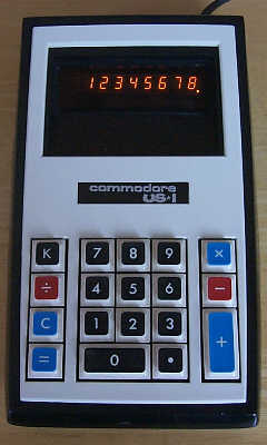
Commodore US*1 Calculator
Updated 7/6/2022
The Commodore US*1 is another example of the fairly extensive line of "US*" display-type calculators marketed by Commodore in the 1972 through 1975 time-frame. Other examples of US* line of display-type calculators in the museum are the Commodore US*1M (exhibit in progress as of this update), US*8 (Version I), US*10, and US*14 calculators. There were other display-type calculators in the line, including the US*3, US*4, US*5, US*5M, US*12, and US*12M. There were also a few printing-type calculators in the US* line, all designated with a P after their model number to indicate that they were printing calculators, including the US*121P, US*150P, US*151P, and US*152P. If you have one of the calculators listed here that isn't in the Old Calculator Museum's collection, and would like to find a new home for it in the museum, please contact us by clicking the Email box in the menu bar at the top of this page.
The US* line of machines distinguished themselves by low-cost, simple construction, and basic functionality. The numeric part of the identifier for the calculators does not necessarily imply the order in which the machines were introduced.
The US*1 is an entry-level, eight digit, automatic floating decimal calculator with constant. It was clear that the US*1 was designed to be a price point calculator, with the primary goal of making the machine inexpensive enough to set a new low-price benchmark for an electronic calculator with basic features to find buyers in the home market. Even though it was an inexpensive calculator (with a list price of $59.95 at introduction, with consistent price drops over its market lifetime) for the time, it is built with a surprisingly high level of quality. Obvious attention was also paid to the design and aesthetics of the calculator, which is in contrast to some of the other calculators in the same market segment.

The Monochromatic Version of the Commodore US*1
As was common with calculators in the US* line, there were at least two variants of the US*1. It is not clear which came first, or if the different versions were available concurrently. The exhibited variant has a colorful keyboard with square key caps on the keyboard. The other variant as shown above has square key caps that taper to a recessed oval area that the finger contacts. The key caps have black bases with a white face, and black nomenclature, making the calculator exhibit a black and white scheme. Otherwise, the two variants were absolutely identical in function. It is not entirely clear why there were different variants of the same model of calculators made by Commodore, but it likely had to do with availability of parts from a variety of manufacturers that provided things like the key caps and cabinetry, with Commodore using whatever materials were available at a given time to keep the production lines going.
Another aspect that is somewhat common within the US* line of calculators is that there were models that have an "M" after their model number. The "M" indicated that the calculator had an added memory functionality that was added to the base calculator. An example of this is the M variant of the exhibited US*1, the Commodore US*1M. As mentioned above, a "P" after the model name indicates that the calculator is equipped with a printer rather than a display.
The US*1 provides the basic four math functions, as well as a switch enabled constant all four functions, which is an unusual feature, even today. Most electronic calculators provide a constant only for multiplication and division.
The US*1 uses algebraic logic, which is also rather uncommon in budget calculators of this time, with a separate [=] key used to calculate the result of an operation. The calculator provides a fully-floating decimal, with the decimal point always positioned to provide the maximum amount of accuracy within the eight-digit display capacity of the machine.
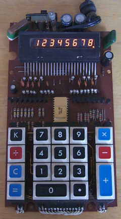
Inside the Commodore US*1
The US*1, along with a number of other calculators from the same general timeline, uses a single-chip calculator IC manufactured by General Instrument. The story behind the development of GI's calculator-on-a-chip technology is quite interesting. The fact is, General Instrument didn't design the chip. Nor did General Instrument design any of the first- generation of the calculator-on-a-chip ICs that it sold to customers as a General Instrument chip. Prior to the introduction of GI's own first calculator on a chip, the company had been doing quite well designing and fabricating calculator chip sets, containing anywhere from eight to four chips that would combine forces to implement the calculator functionality. Most of these chips were custom-designed for various calculator manufacturers, implementing features and capabilities specified by the customer. GI had a crack team of MOS design engineers that had developed the necessary skills to design the calculator logic, segregate the logic across as many chips as it took to hold the logic, and then lay out the chips. Remember, back in the late 1960's and early 1970's, there existed only primitive computer-aided design (CAD) tools for developing integrated circuits, meaning that the the complex five-layer geometries of the chips were taped up using Rubylith and mylar paper on light tables at a scale of 500 times greater than the actual IC features. This meant that the layouts were huge, but absolutely necessary in order to get the accuracy needed once the layouts were photo-reduced to chip size. The chip sets that had been designed thus-far for GI's customers were designed using purpose-built "hard wired" logic, specifically created to implement the functionality the customer desired, and did not follow any computer-like architecture.
A group of General Instrument(GI) employees who had been involved in designing calculator chip sets for GI decided that they wanted to design an entire calculator on a single chip, rather than spreading the logic out across multiple chips in a chip-set. At the point where these folks decided to split off and form their own company to realize their vision. Their last design had taken five chips to implement a calculator chip-set for a GI customer. These designers believed they could put all of the logic of a calculator on a single chip, using techniques taken from the realm of computer design. Rather than using hard-wired logic, their idea was to build a tiny computer on a chip, with enough random access memory (RAM) to hold the working registers of the calculator as well as state information, read-only memory(ROM) to hold the program that makes the device operate as a calculator, an arithmetic-logic unit(ALU) to perform addition and subtraction of numbers in RAM as well as performing logical operations, an input/output section that could read information in from outside the chip (e.g., a keyboard) and output results to some form of display, and a control section that would read the instructions from the ROM, and orchestrate the operation of the functional units of the chip to execute the program.
In the case of using this concept to make a calculator on a chip, the ROM would contain a program that would turn the chip into a full four-function calculator. The program would read from the keyboard, and determine what needed to be done to process the input, update the display as needed, and perform the math operations as commanded, keeping track of the decimal point location, managing the content of the various working registers, and display the result of numeric input or calculations on the display. The beauty of this concept was that the functionality of the calculator lie in the program in the ROM. Adding features or changing the operation of the chip could be done simply by changing the content of the ROM to a different program.
The team had tried to pitch the concept to General Instrument management, but couldn't get traction with it, so in 1967, they decided to go their own way. They started up a company in Glenrothes, Scotland called Pico Electronics, Ltd. While General Instrument management did not believe that the concept of a small CPU embedded in a chip was feasible, especially for use in a calculator, the CEO of General Instrument personally provided the team some startup capital on the condition that if they were successful, GI would be the company to fabricate the chip using their existing processes, and that GI would get first right of refusal to make and market the chip under the GI name. After all, if somehow the Pico Electronics engineers could pull it off, it'd be a market coup for GI, believing that they would have the first "calculator-on-a-chip" to offer to a market ravenous for the technology to make calculators ever-smaller, more powerful, and simpler to manufacture, and of course, at a price that was lower than competitors' calculators.
The Pico team immediately began the process of designing the logic of the chip. Many of the ideas behind the architecture of the chip had already been formed while the team was still at General Instrument, but what had been done thus far was high-level documentation used to try to sell the idea to GI management. Despite that, many of the details of the design had already been formed in the minds of the engineers, so it didn't take that long for them to create a breadboard of the CPU logic using conventional small and medium-scale bipolar and MOS integrated circuits to test out the design. The concepts behind the design were not anything particularly groundbreaking, as the same concepts had been used in the development of larger computers for many years. The true challenge was getting it to all fit on a single chip, with firmware embedded in the ROM that made the chip perform as a calculator.
Test firmware was used to validate each of the functional units of the small computer instead of an actual calculator program, because writing the calculator program a complex task given the modest capabilities of the tiny computer. There was not much RAM nor ROM on the chip, and every single bit of code had to be as efficient as possible to have it fit within the constraints of the CPU. As the chip designers began the task of converting the logic of the breadboard into a single integrated circuit layout, the firmware team was working very hard to develop the code that would program the chip to operate as a basic four function electronic calculator.
After many long days and nights, the chip team had the chip layout ready to send to General Instrument, but it could not yet be sent because one of the last aspects of fabricating the chip involved depositing tiny connections that would permanently set the content of the ROM. In order to make the mask that set the program into the ROM, the code for the chip had to be completed and debugged as best as possible, using the breadboard system to test it out. Fortunately, the timing worked out such that just a short time after the chip layout was ready, the programmers had their first version of the calculator program written and ready. A mask layer was drawn up defining the1 1's and 0's to be coded into the ROM that contained the program code. Finally, the entire chip was ready to be fabricated.
The design was sent off to General Instrument to be fabricated, and in a few weeks Pico Electronics had the very first chips to test. The chips had been parametrically tested, meaning that specific test signals had been sent into the chips, and the outputs measured and compared to expected outputs. If the behavior of the chip didn't match the expected result, it was an indication of a problem. The chips that Pico Electronics received had passed the parametric testing, but the real test was to see if the chip would function as a calculator. A prototype had been prepared for the chip to plug into that provided the power supply, keyboard, and display subsystems. One of the chips was plugged in, and the prototype powered up, and low and behold, it appeared to work! There were a few minor bugs in the programming that required some updates to the ROM, but the chip itself was working perfectly. Unfortunately, the buggy firmware in the chip couldn't be fixed, as the ROM content was permanent. The faulty chips would be destroyed to prevent any possible mistake occurring with chips getting mixed up. The fact that the prototype chips worked at all was truly amazing. The small team of folks in Scotland proved to their former employer that their concept was sound, and able to be relatively easily packed onto a single chip.
Once the final version of the chip was ready for production, General Instrument began manufacturing them in quantity, quickly prepared production-ready data sheets and sales literature for the chip, and introduced it to the market through press releases and trade show presence. It turned out that the chip was not difficult for GI to fabricate, and thus, the chip was quite inexpensive. The processes used to produce it were well-refined at General Instrument, and the design that the Pico Electronics team put together was designed specifically to General Instrument's IC processes, further assuring a relatively easy to produce, low cost chip, much of which was due to its very modular structure. The chip was designated the General Instrument 250. The chip gave no real indication that it was designed by a separate company, but the Pico Electronics guys didn't really care, because a decent portion of the sales price of every chip that General Instrument produced was paid to Pico Electronics as a royalty for their design. The team from Scotland made a handsome profit on their hard work.

A Micro-photograph of the Pico/General Instrument 250 CPU/Calculator on a Chip
As it turned out, another IC company had just barely beaten Pico/General Instrument to market with a single chip calculator IC. Mostek had announced their their now-famous MK6010 calculator-on-a-chip in November of 1970. The MK6010 was developed under contract to the Japanese calculator manufacturer Nippon Calculating Machine Co. (NCM, commonly known as Busicom), based on the hard-wired logic design of an earlier "handheld" calculator that NCM had built using a cleverly-designed batch of small and medium-scale MOS integrated circuits. The MK6010 was designed for one purpose only - to provide the hard-wired functionality of Busicom's earlier calculator. It did not utilize a small CPU-like architecture like the Pico/General Instrument 250 did.
The Mostek MK6010 is heralded in history for being the first commercial calculator-on-a-chip, but it was only available for sale to Nippon Calculating Machine Co. (Busicom) under an exclusivity agreement that was part of the contract that was forged between the two companies, putting it out of reach of other calculator manufacturers. NCM later dropped the exclusivity part of the agreement, and Mostek re-numbered the chip made for everyone (including NCM) as the MK5010 and marketed the chip to anyone who wanted to buy it in production quantities, which also included electronics distributors that would sell the chips at retail prices to anyone. While the Mostek MK6010 was first, the Pico Electronics/General Instrument 250 was a much more flexible design that could easily be extended for different calculator functionality, and even for other uses where a small CPU with its own RAM and program ROM on a chip could be utilized as the intelligence in other types of electronics.
Pico's elegant chip design was patented by Pico Electronics Ltd. as US Patent #4001566A, entitled "Floating Point Calculator with RAM Shift Register", which clearly explains the programmable nature of the chip as it relates to its application as a floating point calculator that operates on eight digit Binary-Coded Decimal Numbers with a ninth guard digit, and a two digit exponent.
An interesting point about the development of the Pico chip was its reliance on the firmware to make the chip function as a calculator. In fact, as the method of using a small CPU with on-board RAM and ROM to implement a calculator on a chip made the firmware become the most difficult aspect of creating a calculator chip, with the actual chip design becoming much less of a chore as a result of the computer-like architecture. Essentially what the Pico Electronics team had designed was a simple microprocessor on a chip that could be programmed via the on-board ROM to perform virtually any kind of function. This capability was demonstrated considerably before Intel (interestingly, also at the request of Nippon Calculating Machine Co.) had developed what became the first commercial general purpose "CPU on a chip", the Intel 4004. The 4004 required external RAM, ROM, and I/O chips in order to operate as a calculator, while the Pico/GI 250 had all of these features integrated together on a single chip. The calculator that Busicom ended up developing with Intel's chip was the Busicom 141-PF, a printing office-oriented desktop calculator. While the 141-PF used the first "CPU on a chip", it required nine other support chips (RAM, ROM, and I/O Shift Register Devices). Regardless of the added complexity of the printing nature of the 141-PF and its larger numeric capacity, it is clear that the Intel 4004 was not truly a "calculator on a chip", but was instead the core of a small CPU on a chip that, combined with other chips, could be programmed to behave as a calculator.
In September of 1971, Texas Instruments announced their calculator on a chip IC, the TMS1802. This device was similar in design to the Pico/GI chip, utilizing a Binary-Coded Decimal Arithmetic Unit, a 182 bit RAM for storing registers and state information, a 3520 bit ROM for storing the calculator configuration and program, a timing and control unit that managed the decoding of the program and activating the various data paths through the CPU, as well as input and output interfaces for connecting to a keyboard and display. Like the Pico/GI chip, the ROM could be mask programmed by generating a layer of connections on the chip to define the content of the ROM. While similar architecturally, the TI device was fabricated on a significantly larger physical chip than the Pico/GI chip.
The Pico/GI 250 calculator IC was initially used in a production calculator in Litton's Royal Digital III calculator, an unusual calculator that had only four digits of display, with a keyboard element that would swap the display between the significant digits beyond four, and the four lower significant digits, providing the capacity of eight digits using a smaller (and therefore less-costly) display. The Digital III, as well as it's eight-digit LED display follow-on calculator, the Digital IV, abandoned the notion of a traditional keyboard by replacing it with conductive metal pads on the circuit board that were exposed through holes in the cabinet that the user would touch with a wired stylus to enter numbers and commands into the calculator. This keyboard arrangement was much less expensive than traditional keyboard designs. Both the Digital III and Digital IV set new low-price benchmarks in the industry, but the Digital III with its limited display, and both the Digital III and Digital IV with their unusual "keyboards" were only mildly successful, with their oddities overshadowing the amazing integrated circuit technology that made them work.
Due to the very flexible design of the 250 chip, Pico Electronics and General Instrument developed and manufactured a number of chips with different ROM code, as well as some enhanced capabilities in the CPU embedded within the chip due to evolution of General Instrument's MOS Large Scale IC processes. A modification of the ROM code resulting in the 251 IC used in the Royal Digital IV and a number of other eight digit calculators for other manufacturers. A bit later, a version of the chip was created that had a larger ROM to hold more complex calculator code, a bit more RAM, as well as some improvements to the CPU architecture that made programming the chip a bit easier.
Commodore was always looking for the latest, least expensive, and simple to implement technology to utilize in the making of the calculators they marketed, and when word of General Instrument's single-chip calculator ICs came to their attention, they immediately jumped at the opportunity to build a calculator that utilized General Instrument's latest calculator chip, the C-500. The C-500 was first introduced in Litton Industries' Royal calculator division's Royal Digital VIII-K calculator, which came to market just a shade before the Commodore US*1, likely because of Litton/Royal's earlier relationship with General Instrument.
The C-500 chip in the Commodore US*1 is plugged into a Molex-style strip socket, which seems unusual for a low-cost calculator, as normally the LSI's were soldered into the board. This makes the chip easily replaceable if there were to be some kind of problem that developed with the chip - a nice serviceability feature. The remainder of the circuitry makes up power supply and display drive circuitry. The planar display is driven with discrete transistor drivers. All of the circuitry of the machine, with exception of the keyboard module, is contained on a single printed circuit board. The circuit board is made of a phenolic material, with circuit traces only on the back side of the board.

Odd Display Behavior When Calculator is Told to Divide by Zero
The US*1 uses a planar gas-discharge display, similar in design to a Burroughs Panaplex panel, but the display is not manufactured by Burroughs. The display uses the standard seven-segment digit arrangement, with a right-hand decimal point included with each digit.
The US*1 exhibited here was built sometime in the 2nd quarter of 1973, based on the date code on the C-500 chip. The calculator is typical in speed for single-chip calculators of this time, with all nine's divided by one taking about 1/3 of a second to complete. The display is not blanked during calculation, and flickers about a bit while calculations are occurring.
As mentioned above, the US*1 offers a constant function on all four math functions. The [K] key is used to set the constant and the type of operation to be performed. For example, to set a constant addition of 1 (turning the calculator into a counter), the user simply presses [1] followed by the [+] key, followed by the [K] key. Then, each successive press of the [=] key will cause the number in the display to be incremented by 1. Similarly, constant multiplication by two would be done by pressing [2], then [X], followed by the [K] key. Once constant operation is set, the only way to clear constant mode is to press the [C] key, clearing the machine and the constant.

Keyboard Detail
The keyboard of the US*1 uses spring-type contacts. The keyboard is a separate module, wired to the main circuit board with individual wires. The key caps are made of plastic, with molded in color and nomenclature. The US*1 opts for a rather patriotic (given the US designation) color scheme for the keyboard, with blue, red, and black background on white key caps, and white nomenclature.
The US*1 forgoes any form of overflow or error detection -- any results in excess of the capacity of the machine are simply discarded. The machine does seem to keep track of decimal point locations up to another 8 digits beyond the end of the display. For example, performing 99999999 X 99999999 results in 99999998, with no decimal point lit. Following this calculation with a division by 10000000 results in 999999998., indicating that the decimal point position was kept track of, even though it was not visible on the display. The US*1 has no input overflow detection, simply ignoring any input in excess of eight digits.

Closer View of General Instrument C-500 LSI and Display Driver Circuitry
The US*1 displays negative numbers by lighting a "-" on the digit preceding the most significant digit in the result. A side-effect of this choice of display method for negative numbers is that the largest negative number that the machine can accurately represent is -9999999, losing a digit of display to the '-' sign.
Performing division by zero on this machine causes an interesting counting effect, with the least-significant digit counting very quickly such that it looks like an 8, with some of the segments flickering ever-so-slightly, and the third digit from the right counting where it's easy to recognize the digits as they count off. All of the decimal points light up, and the digits that aren't counting show digits that somewhat relate to the divisor. The only way to exit this state is to press the [C] key to clear the calculator, or to power it off, wait a few seconds, then power it back on again. A static example of this behavior is shown in the image of the display above.