
| +Home | Museum | Wanted | Specs | Previous | Next |

Canon 130S Calculator
Updated 2/28/2024
The Canon 130S is a refinement of Canon's first-generation electronic calculators, which included the Canon 130(Canon's first electronic calculator), the Canon 151, and the Canon 161. The 130S also had a "little brother" model called the Canon 120 that provided 12 digits versus the 13 digits of the 130S, as well as omitting some of the 130S's features. The 130S is essentially a smaller (more densely packaged), lighter, and somewhat functionally improved version of Canon's first machine, the Canon 130. Although the 130S is more compact than its predecessor, it shares a very similar architecture and the unique-to-the-industry electro-optical display technology of its ancestors.
Canon's entry into the electronic calculator business was driven by its own internal need for performing complex mathematical calculations related to optics, as Canon's primary business at the time was manufacturing high-quality cameras and other precision optical instruments. While an electronic calculating machine could help the company with its scientific calculations, it could also serve as a lucrative new business for the company, which proved to be a fantastic business move, as Canon, to this day, is a major player in the electronic calculator marketplace. It wasn't a simple matter to convince Canon's management that the calculator business was right for the company. Though the prototype machines proved very useful to Canon's engineers working on lens and optical system design, it took a daring yet successful showing of one of the Canon 130 prototypes at a Japanese business machine show to convince Canon's management that productizing these internally-developed machines was worth the investment. The result was the introduction of the Canon 130 in 1964. The success of the 130 led to future calculator developments, leading to market leadership that to this day, still makes Canon a key player in the business calculator market.

Ad Touting the "Lightweight" and Portable Nature of the New Canon 130S (Click image for larger view)
The 130S differs from Canon's earlier calculators mostly by virtue of improved packaging efficiencies. The density of components on the circuit boards in the 130S is significantly greater than that of the earlier machines. The electro-optical display modules are mounted directly to the circuit boards, with some boards having two display modules attached. Earlier calculator models had a separate display subsystem, which required a complex cable harness to connect the display to the logic. The display modules are more compact, and also designed to be easier to service (lamp replacement) than the earlier machines. The backplane is more dense, with each circuit board having more connections to other circuit boards through the backplane. In general, the components of the 130S (power supply, keyboard, logic card cage, etc.) are designed to be more conscious of the space they consume. To reduce weight, the upper part of the cabinet of the 130S is fashioned from sturdy plastic rather than the all-metal cabinetry of its predecessors, although the base of the 130S is still made from a stout metal casting. All of these factors combine to make the 130S a significantly smaller, somewhat lighter, and more capable version of the original 130. The decrease in size and weight featured prominently in advertising for the machine.

The Canon 130, Canon's First Electronic Calculator
Like Canon's original calculators, the 130S is an all-transistor design. All the logic and storage elements are made up of discrete semiconductor transistorized circuits. Calculators made by other manufacturers during this time-frame generally utilized other means for storage of working registers, such as magnetostrictive delay lines, magnetic discs or drums, magnetic core memory, or capacitive storage. Typically these other technologies were less-expensive than pure transistorized storage, as they tended to reduce component count, had better space efficiency (packing more storage into a smaller space), or both.
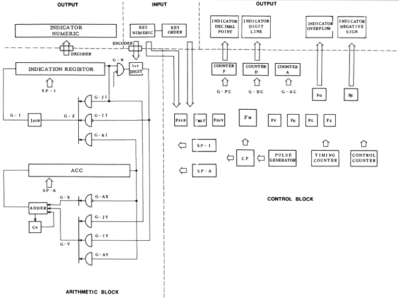
Block Diagram of the Logic of the Canon 130S
Apparently Canon engineers were most comfortable with a design that avoided these potentially temperamental memory devices, and settled with a completely solid-state transistorized design. All of the working registers in the 130S are composed of transistor-based flip-flop shift registers. With all transistorized working storage and individual decoding and driving circuits for each digit, the component count in the 130S is quite high, with a total of 545 Hitachi-manufactured Germanium transistors making up the active logic of the machine.

A view of 130S Electro-Optical Display in operation
Because of the electro-optical display technology, which is too "slow" to be able to take advantage of multiplexing techniques, the machine is designed with static display logic. All but the earliest electronic calculators utilized a dynamic operational mode, by which the data is continually circulating through the logic, even when from the user's standpoint the machine is idle. This technique significantly reduces component count by timesharing (multiplexing) the display decoding and driving circuitry. The 130S (and earlier Canon calculators) utilize a "start/stop" mode of operation. The registers of the machine remain static when the machine is not being exercised by the user. Once the user initiates an operation, the data begins circulating through the working registers of the machine as the operation is performed. Once an operation is completed, either the result is already in the display register (such as when numeric entry is performed) or, in the case of completion of a mathematical operation, the result is shifted into the display register. The content of the display register is decoded by individual per-digit decoding circuitry, and is shown in the display. The fully-transistorized nature of the Canon calculator's architecture allows such a mode of operation to function, as other types of register storage (such as magnetostrictive delay lines) typically impose strict and continuous timing requirements on the cycling of the logic.
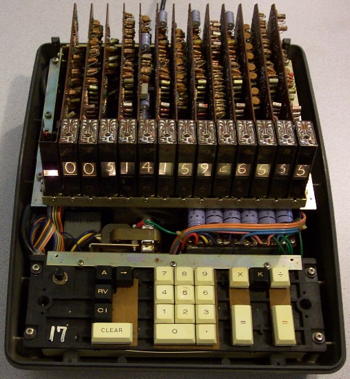
The Canon 130S with top cabinet and keyboard bezel removed
The logic of the Canon 130S is contained on thirteen printed circuit boards, which are somewhat irregularly shaped, but overall, measuring approx. 8" X 5". Each board contains components on one side of the board, and etched interconnects on the other side of the board. Jumper wires on the component side of some of the boards make up for shortages of interconnect real-estate on the connection side of the boards. The boards are made of standard phenolic, copper-clad on one side, etched with usual circuit board manufacturing processes. There is no through hole plating.


Boards 1 through 4 (Board 1 is the right-most board in the card cage) (click board image to enlarge)
Boards 5 through 8 (click board image to enlarge)
Boards 9 through 12 (click board image to enlarge)
Board 13 (click board image to enlarge)
Each board has two
extensions for edge connector fingers, although both connectors aren't
always used. An unusual feature is that the edge connector finger pitch
varies depending on the number of signals that must be made external to
the card. Some cards that have need for only a few connections populate
only one connector with .200" finger spacing, while other cards
requiring more connections populate one connector with .200" spacing,
and the other with .100" spacing. In cases where an edge connector extension
is not used, the backplane has a socket populated with no contacts.
The card's edge connector fingers plug into sockets that interconnect the
cards via a beautifully crafted hand-wired backplane. The circuit boards,
unlike earlier Canon machines whose cards plug in horizontally, plug in
vertically. In most cases, the signal names of the function of each edge
connector finger are marked in white silk-screen on the circuit board.
Other information helpful to service technicians, such as the function
of various logical groupings of components are also marked in white
silk-screen on the boards. Such thoughtfulness makes it easier for
preservationists in the future to troubleshoot and repair these wonderful
old machines. Fortunately in the case of this machine, other than a number
of burned out lamps in the display modules, and some power supply capacitors
that needed reformation, the machine still worked properly when received.
The base of the Canon 130S. Note rubber rollers for easily moving calculator on desktop. Mechanically the 130S is built
in a similar fashion to the earlier machines, with a very sturdy
metal chassis. The main savings in weight is the plastic upper-cabinet, which
is made from very high-quality molded ABS plastic. While not giving
quite as much of a feeling of sturdiness as the all-metal cases of the
earlier machines, the plastic case is well designed, and gives off a strong
feeling of quality. The upper
cabinet is made of two pieces, one covering the electronics
card cage and serving as the display panel. The second piece makes up the
keyboard bezel. The two sections
are molded such that there is a nearly seamless boundary between them.
The keyboard bezel is held in place by two screws located underneath
the front of the keyboard bezel. Once these screws are removed, the keyboard
bezel can be lifted off. This exposes two screws underneath which secure
the front part of main cabinet, along with two screws on the back panel of
the machine. Once the four screws are removed, the main cabinet can
lifted straight up and off the chassis.
Side, Front, and Top Views, and Light Guide of Display Module for Canon 130S From a serviceability standpoint,
the 130S is a significant improvement over the earlier machines. Given that
the display modules are mounted on the circuit boards, it is a rather
simple matter of removing the two top retaining brackets that keep the circuit
boards in place (a total of eight screws), and loosening one or two (depending
on whether the circuit board has one or two attached display modules) display
module retaining screws, and sliding the circuit board out of the chassis.
The edge connector sockets have a strong grip, so it is usually necessary to
use a tool to gently pry on a number of different leverage points on the
circuit boards to loosen the board from their grip. The display modules
hang on brackets mounted to the circuit board, requiring only that the
display module be lifted up and slightly back to uncouple it from its
mounting bracket. There is sufficient extra cable connecting the display
module to the circuit board to allow the display module to be easily worked
on.
Lamp Circuit Board Module
The display modules are significantly easier to service than those of the
earlier calculators. This is a major improvement, as incandescent display
lamps tend to burn out in significantly shorter periods of time than other
types of display technology used in early calculators (e.g., Nixie Tubes).
Each digit display module has two lamp circuit boards, one at the top, and
one at the bottom of the display module. Each lamp circuit board contains
six small incandescent lamps. These lamp circuit boards are held in place
in the display module by a single tiny slotted-head screw, which, when
removed, allows the lamp board to be pulled out of the display assembly,
exposing the lamps. A total of seven wires connect each lamp circuit board
to the logic board, one common line, and six individual wires for each of
the lamps. Each lamp's two leads are individually soldered to through
pads on the lamp circuit board, making it a relatively
simple operation to de-solder a failed lamp and replace it, without having to
fiddle with the wiring. Printed circuit traces on the lamp board connect the
wires from the logic board to the lamps.
Canon 130S Test Fixture Connector
To add to the serviceability, the 130S has provisions for connection of an
external test fixture that can provide controlled clocking and monitoring
of various major logic states. A special 22-pin edge connector at the left end
of the card-cage provides connection for a test fixture device. A slide
switch located on circuit board #9 (which contains the master clock
oscillator), allows the master clock signal to be
disabled so that injection of clock pulses can come from the test fixture.
With the test fixture in place, it is possible to manually generate
master clock pulses one at a time, or in cycle groups, stepping the
machine through its various cycles at an observable rate to assist with
troubleshooting.
Each display module contains the digits
zero through nine, a right-hand decimal point, and a right-hand vertical
bar, for a total of twelve different
indications. The vertical bar is used as
a separator between multiplicand and multiplier in multiplication operations.
Unlike the earlier Canon calculators, the vertical bar indicators are not used
for grouping integers into groups of three for easier reading. Why this
feature was omitted on the 130S is not clear, but was likely a simplification
to reduce cost. Replacing this digit grouping function are four small plastic
sliders below the display panel that the user can manually position to help
group the display digits for easier reading.
The display lamps operate on approximately 13V DC.
Each display digit has its own decoder/driver circuitry, connected to one
four-bit stage of a 56-bit display shift register (of which some bits are
used for housekeeping functions). A blanking signal allows all of the
displays to be inhibited while data is being clocked into the display shift
register. Unlike the earlier machines, the 130S properly handles negative
numbers as a true negative number rather than as a tens complement value, a
significant improvement for use of the machine in business environments.
Canon 130S Power Supply
As with the earlier machines, the majority of the rear section of the machine
is consumed by the logic circuitry. The front area of
the calculator contains the power supply and
the keyboard assembly. The power supply is very similar in design to that of
the earlier calculators, with a transformer converting AC line voltage to
lower-voltage AC, diode rectifier bridges converting the AC to DC,
and capacitive filters smoothing the rectifier ripple. High wattage
variable resistors set the rough DC voltage levels, and transistorized
regulators keep the voltages consistent with varying loads as the logic
cycles. Among the power supply circuitry is a small fan driven by an AC
motor that pulls air through vents in the bottom part of the chassis and
directs it upward through the electronics and out vents in the side and upper
surfaces of the cabinet for cooling beyond natural convection. The fan keeps
the machine running much cooler than convection-only cooling would allow.
Leaf-Switch Keyboard Assembly of Canon 130S
The keyboard assembly is
virtually identical to that of the earlier machines, with a
hefty plastic molded chassis, and plastic molded key-stalks that actuate
leaf switches. The keyboard assembly is attached to the base by
a total of four screws. Slightly slotted holes in the keyboard chassis
allow fine positioning of the keyboard assembly to assure no interference
between the key caps at the keyboard bezel. The key caps are double-shot
injection-molded plastic, meaning that the nomenclature of each key is
molded into the key, assuring that it will never wear off even after many
years of service. A light spring located underneath each key cap, along
with the spring action of the leaf switch itself provides a positive return
for each key when the it is released. The keyboard connects into the
backplane through a hand-wired and laced cable, with enough slack in it
to allow the keyboard assembly to be removed from the chassis for
service without having to unsolder any connections. The underside of
the keyboard assembly (circuit board and leaf switches) is protected by
a plastic cover which is secured with a number of screws. This cover
helps keep dust and other atmospheric contaminants away from the switch
contacts due to the action of the cooling fan creating airflow through the
chassis. Due to the electronically "bouncy" nature of leaf-switch type
contacts, Canon utilized a unique and patented circuit which eliminates
the transient signals from the key-switches, and also causes keyboard lockout
(and lighting of the overflow indicator) if more than one key is pressed
at the same time, preventing the possibility of erroneous entry in such
conditions.
Detail of the Canon 130S Keyboard The 130S provides
the four basic math functions, along with an accumulation mode for products
and quotients. Addition and subtraction are performed using
two [=] keys, one [=] in black for addition, and the other
[=] in red, for subtraction. Multiplication
problems are entered as expected, by entering
the multiplicand, pressing the [X] key, entering the multiplier, then pressing
the black [=] key to calculate the result. Like the earlier Canon machines,
the display of multiplication problems is unusual, with both the multiplicand
and multiplier on the display at the same time.
The 130S uses a special indication in the display for multiplication --
a green-tinted vertical bar situated to the right of the last digit of the
multiplicand -- to separate the multiplicand from the multiplier on the display.
For example, performing 12 X 768 would end up showing up on the display
as "0000000012|768." before depressing the [=] key, with
the vertical bar representing the multiplication indicator. Like the earlier
machines, the 130S can not display multiple decimal points on the
display at once (the decimal point logic is a '1 of 13' decoder), so
performing multiplications with operands that both contain decimals can look
confusing on the display. For example, performing "12.203 X 101.345" would
display as "0012.203|101345". Even with this anomolous display, the correct
answer is given when the [=] key is pressed to complete the calculation.
The machine keeps track of the location of the multiplier's decimal point
internally without displaying it. Division operates conventionally, with
the black [=] key displaying the result. The [RV] key reverses the order
of the two operands for multiplcation and division operations.
The push-on/push off [AM] key emables the accumulation of products/quotients
in the main accumulator as long as the key is in the depressed position. The
push-on/push-off [K] key provides for a constant for use in multiplication
and division operations. The multiplicand in multiplication or
the divisor in division is retained as the constant, and may be re-used
in subsequent calculations as long as the [K] key is locked in the depressed
position. For example, with the [K] key depressed, entering 12 X 7 and
pressing the [=] key results in "0000000000014." in the display. Then pressing
[6] will cause "12|6" to be displayed, with the "12" constant being recalled
followed by the multiplication symbol, then the new multiplier "6". Pressing
[=] results in "0000000000072." in the display, the result of 12 X 6. An example
of division would be 12 ÷ 3 (entering "3" as the constant), which would result
in "0000004.000000". Then pressing 21, followed by [=] would result in
"0000007.000000", showing that the "3" divisor was retained for the second
calculation (21 ÷ 3).
Beautifully hand-wired backplane harness & connectors The 130S provides automatic floating
decimal point placement logic, with improved operation over earlier modes, which
exhibited some limitations. For addition and subtraction, the argument with
the most digits behind the decimal sets
the decimal point location for the result. For example, performing
12.6005 + 14.10000 will result in a display of "00000026.70050", with the
"14.10000" input (even with insignicant trailing zeroes) setting the decimal
point location at five digits behind the decimal. For multiplication, the
decimal point is set at the location defined by the count of digits behind
the decimal in both the multiplicand and the multiplier. For example,
performing 12.25 X 3.004 will result in "00000036.79900" being displayed, with
five digits behind the decimal point set by the fact that there are a total
of five digits behind the decimal in the multiplicand and multiplier. As
this example indicates, the calculator does not perform trailing zero
suppression. For division operations, the maximum number of digits behind
the decimal point for any operation is seven. Performing
1 ÷ 3 will result in "000000.3333333". With larger operands in the division
operation, the number of digits behind the decimal in the result will
decrease. As an example of this, performing 1600 ÷ 8 will result in
"000000200.0000". Even calculations which result in no fractional answer
will have digits trailing the decimal, as in 12 ÷ 6, which will
display a result of "000002.000000". Six digits appear behind the decimal
in the result because there are two significant digits in the divisor,
which decreases the available number of digits behind the decimal to six
from the maximum of seven.
The remaining keyboard functions include
the [CLEAR] key, which clears the entire machine. The 130S does not have
a "power-on" clear function, which means that when the machine is first turned
on, garbage may be contained in the machine's registers, and its logic
state may be undefined. Pressing the [CLEAR] key before performing any
operations when the machine is first turned on assures that the machine's
state is made consistent, and all registers are cleared and ready for
operation. The [→] key
performs two functions. First, it can be used to position a number on the
display by shifting it to the right. This can be used to trim off trailing
insignificant digits, truncating any result
to a user-desired number of digits. An example
of the use of this would be to trim the result of a division down two a few
significant digits, such as if the user performed 2 ÷ 3, and wanted the
result only to three decimal places. The machine would provide
"000000.6666666" as the result. Pressing the [&rarr] key
four times would shift the least-significant digits off the display,
resulting on '0000000000.666' when finished. There is no logic to prevent
the decimal point from being shifted "off the end" of the display, in which
case the decimal point will appear after the most significant digit in the
display, and continue to be shifted to the right after each depression of
the [→] key. As an example, pressing the [→] key five more times
after the "0000000000.666" result above would result in "00.00000000000"
in the display. The primary function of the [→] key, however, is
for use to correct numeric entry errors, by 'backing out' entered numbers
a digit at a time for each depression of the key.
A special display module located at the left
end of the display provides overflow and sign indication.
The 130S indicates overflow a red-colored left-pointing arrow.
This indicator will light when the machine
is overflowed either by excessive input, or by operations which exceed the
capacity of the machine. This indicator also lights when the keyboard
is logically locked-out due to simultaneous depression of more than one key at a time.
Below the overflow indicator the sign indicator, which lights up "-" when
the number in the display is negative.
Canon claims that the maximum calculation
time for addition and subtraction is 80 milliseconds. That's a bit slow
compared to competitor's machines of the time, but Canon was honest in quoting
maximum performance figures, with average performance coming in significantly
quicker. Maximum calculating time for multiplication is 0.8 seconds, again
rather slow. Interestingly, division is quoted as taking a maximum of
0.5 seconds. Division (usually all 9's divided by 1 as the worst-case
calculation) typically has longer worst-case times than multiplication. Why
division runs quicker than multiplication is a bit of a mystery.
By observation, the machine is about average in speed for its time.
Addition and subtraction occur almost instantly, with only a slight flicker
of the display indicating that the operation takes any time at all.
Multiplication clearly offers more of a challenge to the machine, with
999999 X 999999 (worst-case) taking approximately 1/2 second to reckon (about
0.3 seconds quicker than quoted). Division is the slowest of the
operations, with 999999999 ÷ 1 taking approximately 1 second to provide an
answer. This bears out the fact that division does take longer in worst-case
calculations than multiplication. The reason that the worst-case division
operation mentioned above contains only nine 9's is that
number is the maximum sized dividend that can be used. This
is because of the way that the calculator shifts the dividend to the
most-significant digits before the divisor is entered. Due to the decimal
placement logic, this limits division to dividends with no more than nine digits
in front of the decimal point. Performing division operations with more than
nine digit (in front of the decimal) dividends results in results with
incorrect decimal point placement, or flat-out wrong answers.
During calculation, the displays are blanked, leaving the dancing of the
digits an exercise of the imagination of the user. Dividing by zero is not
trapped by overflow detection logic. The result of attempting this operation
is that the calculator hangs, requiring a press of the [CLEAR] key to
restore normal operation.
Model/Serial Identification Tag The Canon 130S proved to be a bridge
machine between Canon's first-generation calculators, and the following
generation which started with the
Canon 141, the first Canon calculator to utilize integrated circuit technology to further shink the footprint
of a desktop calculator, as well as making the machines more portable
through lighter weight.


