
| +Home | Museum | Wanted | Specs | Previous | Next |
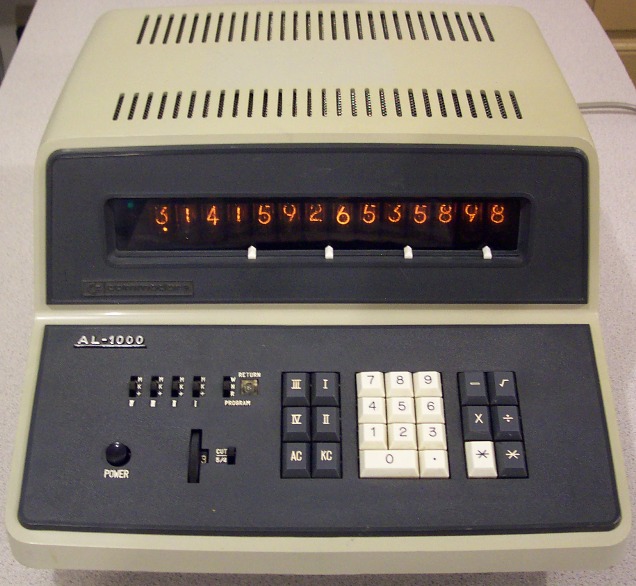
Commodore (Casio) AL-1000 Programmable Calculator
Updated 10/16/2022
The Commodore AL-1000 is a truly amazing and interesting machine for its time. It's definitely an extension of the architecture of the earlier Casio 101E (also marketed by Commodore as the Commodore 500E.), but with additional memory through use of a magnetic core memory, addition of a square root function, and most notably, the implementation of a rudimentary programming capability. Casio claims that the AL-1000 was the world's first programmable electronic calculator, a claim that is clearly not valid, but the Al-1000 is certainly among the earliest stored program programmable calculators. Mathatronics, Inc. and their Mathatron calculators (circa late 1964) lay legitimate claim to the title of the world's first stored-program programmable electronic desktop calculator, almost three full years before the AL-1000 was introduced in Japan in October of 1967.
If you are confused by the references to Casio, it is understandable. The credit for the design of the AL-1000 doesn't belong to Commodore. Commodore had license to purchase the calculators from Casio without serial number tags or Casio badges and put on their own badging, and sell the calculator in North America under the Commodore label. The design and construction of the AL-1000 was performed entirely by Casio in Japan. Commodore simply imported the machines, placed Commodore identification badging on them, and marketed, sold and provided service for the AL-1000 as if it were their own.
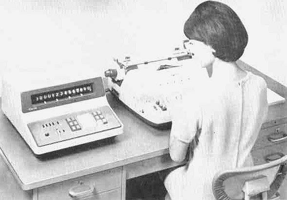
Casio AL-1000S w/Adler I/O typewriter
Casio produced an enhanced version of the AL-1000, designated the AL-1000S, that added an interface to a modified external electric typewriter, allowing full operation of the calculator from the typewriter, as well as providing printed output for all calculations performed by the machine. It is not clear if Commodore also marketed the AL-1000S as part of their offering in North America. No documentation has been found thus-far to indicate that the AL-1000S was marketed by Commodore. If a reader of this exhibit happens to know of such documentation, please contact the Old Calculator Museum by clicking the Email button at the top of the page. The Casio AL-1000S model, complete with the I/O interface and external I/O typewriter cost around US$1,300 more than the base AL-1000's base price of $1,495. Casio offered a number of different modified typewriters for use with the AL-1000S. Casio also offered a service to custom-modify any capable customer-provided electric typewriter for use with the calculator.

A profile view of the Commodore AL-1000
Date codes on the transistors in the exhibited machine indicate that it was built in the mid-1968 time frame. This places the machine close to the end of the era of all-transistor discrete component calculators. Just a matter of months later, early Small-Scale IC-based calculators started showing up in the marketplace, marking the beginning of the end of the all-discrete component electronic calculator. Considering the Mathatronics Mathatron was more capable and developed much earlier than the AL-1000, and also accounting for the fact that Hewlett Packard's revolutionary 9100A programmable scientific calculator was introduced around the same time as this particular machine was produced, indicates that the Japanese clearly had some serious catch-up to play in terms of offering advanced programmability features in their calculators.

AL-1000 Keyboard Detail
The AL-1000 is a 14-digit machine, performing the basic four math functions along with one-key automatic square root. The machine has four memory registers, each of which can be set up as accumulators, store/recall registers, or read-only constant registers. The memory registers are designated [I] through [IV], and are controlled by keyboard keys with the same nomenclature. The two working registers of the calculator, along with the memory registers, and 30 steps of stored program reside in a 14x8x4 magnetic core memory array, meaning that the content of the memories and program steps are maintained when power is removed from the machine. The two working registers are automatically cleared at power-up, though. Memories I and II are full fourteen-digit with sign and decimal point storage registers while memories III and IV are limited to seven digit integers. The memory registers are activated by simply pressing the key corresponding to the memory register to be operated upon. There function of the memory registers is controlled by a bank of four three-position slide switches. Each slide switch has an accumulation mode (+), Read-Only (K), and Memory (M) position. When the mode switch for a memory register is in the (+) position, the corresponding memory register acts as an accumulator, adding the number in the display to the memory register when the memory key is pressed. When in the (K) position, the corresponding memory register is made read-only, causing the content of the memory register to be recalled to the display when the memory key is pressed, useful for storing frequently used constants. For example, the value of the constant e can be stored in memory register I, and with the memory mode switch subsequently moved to the (K) position. In this case, the memory register is locked from changes as long as the mode switch remains in the K position (even though power cycles), effectively preserving the constant until the memory mode is changed and the constant over-written. Lastly, the Memory (M) position of the memory mode switch causes the memory register to become a store/recall register, storing the content of the display in the memory register when the memory key is pressed, and recalling the memory register to the display when pressed after a function key. It should be noted that memory register II is used by the division function, with division operations corrupting the content of memory register II. This means that memory register II should not be used within programs that perform any division operations, as any content will be mangled when the division operation is performed. Attempting to store a number larger than seven digits in memory registers III and IV result in the number being truncated to seven digits.
The AL-1000 uses NEC-made Nixie tube displays, with each tube containing the digits zero through nine along with a right-hand decimal point. The calculator provides full floating decimal point location, which is a rarity for electronic calculators of this time period. A thumb-wheel switch on the keyboard panel provides a setting for specifying the number of digits behind the decimal point that are to be retained for round-off/truncate operations. This thumb-wheel switch has settings for 0 to 8, and ↓ Setting this thumb-wheel to any of the zero through eight positions selects how many digits behind the decimal point results will be rounded or truncated to. A slide switch next to the thumb-wheel selects whether truncation or round-off/up occurs at the selected digit position. To activate the rounding operation, the gray [*] key is used rather than the white [*] key to complete a multiplication or division operation, or anytime before clearing or entering digits into the machine.

The insides of the Commodore AL-1000
Operation of the machine is conventional, though the nomenclature on the add/subtract keys is not entirely obvious. Addition and subtraction are performed in arithmetic fashion, with a white [*] key performing addition, and a gray-colored key with the same [*] nomenclature performing subtraction. Multiplication and division operate as expected, with the white [*] key generating the result. The [√] key calculates the square root of the number currently on the display, accurate to 13 digits. There are two keys for clearing the calculator; one labeled [AC] which performs a master clear of the machine (except for the memory registers and program step storage), and the [KC] key, which clears the display only, allowing for correction of incorrectly-entered numbers. The [-] key provides a change sign function, but not quite in the usual sense. On most machines, this function serves as a toggle, where each successive press toggles the state of the sign, e.g., one press, number made negative, a successive press will switch it back to positive, etc. On the AL-1000, pressing the key causes the number to be made negative, and the only way to undo the operation is to clear the entry register (with the [KC] key), and start over.


Board 1 and 2 (Display, Keyboard Encoding) [Click on image for larger view]
Internally, the AL-1000 is quite complex considering that it uses magnetic core memory for its register storage versus the discrete transistor flip-flops used in the earlier Casio 101E. The circuitry occupies a total of ten rather large 12 1/2" X 7" phenolic circuit boards. The circuit boards have traces on both sides, with feed-through to interconnect traces on both sides of the board formed by a short length of wire put through the feed-through hole, and soldered in place. Some boards have wire jumpers on them, in cases where the trace density was too high to be able to have circuit board traces to make the connections. Each board is packed full of discrete components, with diode-resistor gating, and transistors for flip flops and other active logic elements. A total of 430 transistors and 1300 diodes make up the complement of active devices in the logic chassis of the calculator. The AL-1000 uses a standard set of transistors, with most of the transistors in the machine's logic utilizing 2SC371 and 2SC641 devices.

AL-1000 Backplane (Note Gold-Plated Edge Connector Sockets)
The circuit boards plug into edge connectors that are wired together by hand to form a backplane to allow signals to pass from board to board. The calculator features a somewhat modular design, with each circuit board in general performing a function, or a portion of a function. The designers were thoughtful enough to include silk-screened nomenclature on most of the boards identifying their function. Unfortunately, the keyboard is hard-wired into the backplane, meaning that replacement of the keyboard assembly requires de-soldering of myriad connections from the backplane, and re-soldering new connections from a replacement keyboard. Many contemporaries of the AL-1000 provided an edge-connector connection for the keyboard assembly, making keyboard replacement a simple operation. The power supply section is also hard-wired, making it a bit of a task to replace the power supply. Given these limitations, service technicians likely had to have a pretty strong knowledge of the way the machines worked, as well as how they were put together, in order to perform service.


Board 3 and 4 (Main 1, Main 2) [Click on image for larger view]
The boards are numbered, front to back, from 1 through 10. Designations on the boards indicate the internal Casio model designation (in this case, 14B), followed by a dash, followed by the circuit board number, followed by a space, and then the boards revision code (beginning with A and progressing through the alphabet) inside a circle.


Top: Early AL-1000 Keyboard Structure Made from Cast Aluminum
Bottom: Later AL-1000 Keyboard Structure made from Cast Plastic
The museum has three AL-1000's, and it is clear that even though the units are relatively close to one another by serial number (50923, 51294 and 51601), there were definitely some changes made between the calculators in the museum's collection.. Some circuit boards in the unit with the higher serial numbers have one revision level higher circuit boards. Also, the higher serial-numbered machine has a plastic casting as the framework for the keyboard assembly, while the lower serial-numbered units use a cast aluminum framework. There are also some differences in the power supplies between the units, with mounting of the main logic supply regulation pass-transistor and electrolytic filter capacitor being somewhat different, with the later serial-numbered unit having a less complex mounting arrangement. It's clear at least the keyboard hardware and power supply mounting changes were made to reduce cost and make assembly more efficient. The circuit board revisions may have been made to improve reliability, improve assembly efficiency, or eliminate "bugs" in the design.
The The front-most board (#1) is the display board, containing the display decoding logic, Nixie tube driver circuits, and the Nixie tubes themselves. The next board doesn't have any nomenclature on it indicating its function, but it contains circuitry related to keyboard conditioning and encoding, as well as the decimal point position counter and its logic.. The next three boards (Boards #3, #4 and #5) are designated with "MAIN" (MAIN 1, MAIN 2, and MAIN 3). These boards contain most of the control logic of the machine. There boards contain the function code latch, function code decoding, various state flip flops, the state sequencing logic and the major state latches, as well as the next state generation logic.


Board 5 and 6 (Main 3, "Sub")
Board six has nomenclature on it reading "SUB", which doesn't give much of a clue as to its function. This board contains the the master clock generation circuitry (approximately 66KHz), core memory read/write timing signal generation, and state clocking logic.
The next board (#7) carries "ADDER" nomenclature, which makes its function relatively obvious. This board contains two four-bit latches that carry the two digits to be operated upon by the 4-bit parallel adder circuitry. The adder sums the two numbers in the latches into a four bit result along with a carry flip flop that is included in the addition, as well as being set after the addition if the sum of the two numbers is greater than 9. The adder logic is quite complicated, as it has to account for correcting sums that are greater than 9 into the proper BCD digit and setting the carry flip-flop. The adder does this by adding six to any result that is greater than 9. For example, if the two numbers in the adder latches are 7 (0111) and 9 (1001), the binary sum of these two numbers is (noting any carry out of the most significant bit) is 0000 (0) with a carry out of the most significant bit. Clearly, 0 is not the sum of 9 and 7. This is where the "add six" correction logic kicks in. The carry triggers the "add six" circuitry which takes the result (0000) and adds six(0110) to it, resulting in 0110, which, is 6, the correct low-order digit of adding 9 and 7. Activation of the "add six" circuit also sets the inter-digit carry flip flip, which when set will add one to the sum of the next addition performed, effectively adding the tens digit of the result of adding 9 and 7 (which is 16) to the next set of digits being added.


Board 7 and 8 (Adder, Addressing Logic)
Board #8, which has "ADDRESS" nomenclature silk-screened on it, contains the digit counter, which is used to keeping track of which digit in the number a keyboard digit entry will be placed into. There is also a decoder that generates individual outputs for the various possible digit settings of the digit counter used for addressing the digit in the input register (which is maintained in core memory with the rest of the calculator's registers). The board also contains some of the core memory address generation logic related to selecting the base address in the core memory in which a given register is contained.
The next board (Board #9) is aptly labeled "DRIVE". This board contains circuitry to drive the X and Y wires in the magnetic core array. Magnetic core memory operates by having wires strung in an X and Y grid, with a magnetic core at the intersection of each of the wires. By putting a pulse of current through an X wire and a Y wire, with each pulse being 1/2 of the of current it takes to generate a sufficient magnetic field to flip the state of a core. The magnetic core at the intersection of the two wires will receive a big enough magnetic field generated by the combined current pulses to change its state from a 1 to a 0, or a 0 to a 1, depending on the direction of the current flow through the wires. The other cores on the X and Y wires only see half of the magnetic field necessary to change state, so they remain in their existing state. The current pulse that is generated has specific characteristics in terms of its rise and fall time, as well finely tuned as far as the amount current is delivered. The core memory array used in the AL-1000 uses what area called pulse transformers to help create the current pulses. These are the black boxes with the light blue surround on them.


Board 9 and 10 (Core Drive, Core Array)
Board #10 is the rear-most board in the card cage, is the core memory board. The core array is located in the middle of the board, and is covered by a Plexiglas shield to protect the delicate cores and wiring from damage. The remainder of the circuitry on the core array board contains the sense amplifiers and the inhibit drivers. Since there are four identical arrays, with each array containing one of the four bits that the core memory delivers at at time. Because of this, there are four identical sense amplifiers and four identical inhibit drivers.
The core memory contains a total of 448 bits, logically arranged as eight 14-digit registers, or a total of 112 binary-coded decimal(BCD) digits. The working registers of the machine, program steps, and the memory register content are all stored in the core memory. At power-up, the working registers are cleared, but the program and memory register content is retained. Data is stored in core in the form of 4-bit BCD digits. The core is physically arranged as four separate 14 X 8 arrays, with each array storing one of the bits of a BCD number (e.g.,: one array holds the 20 bits, another holds the 21 bits, etc.). Sixteen digits are used for each of the two working registers as well as for memory registers I and II. In each of these registers, fourteen digits are used to represent the number in the register, one digit is used to represent the sign of the number in the register, and one more digit represents the position of the decimal point in the number. 30 digits are used for storing program steps, with two digits used to keep track of the current program step number. Lastly, seven digits are used for memory registers III and IV, with one additional digit for each of these two registers defining the decimal point location within the number. All told, the two working registers consume 32 digits, memory registers I and II consume 32 more digits (64 digits used so far), memory registers III and IV each consuming 8 digits (brining the total to 80 digits), and the program step storage and program counter consuming 32 more digits, for a grand total of 112 digits -- the full capacity of the core memory array.

Close-up view of Core Memory Array
The AL-1000 is programmable, albeit in a very simple, limited, and somewhat unusual fashion. The programming function operates in a semi-'learn-mode', where key press sequences of up to 30 steps can be keyed into memory and later replayed automatically. Most 'learn-mode' calculators store key presses as codes in memory, as each key is pressed. On the AL-1000, the user types in special numeric codes for the functions that are to be stored as program steps. The codes are made up of the digits 1 through 9, with five other codes formed by entering the digits 2, 3, 4, 6, and 7 followed by a decimal point. The codes used are shown in the following table:
0  No Operation
1  Change Sign [-]
2  Add         [*] (white)
3  Subtract    [*] (gray}
4  Memory I    [I]
5  Memory II   [II]
6  Memory III  [III]
7  Memory IV   [IV]
8  Multiply    [X]
9  Divide      [÷]
2. All Clear   [AC]
3. Clear Entry [KC]
4. Square Root
5. Undefined (Causes Program to Hang)
6. Stop (data entry)
7. End Program

AL-1000 Program Code "Quick Reference" Card
A three position slide switch controls the the operating mode of the calculator. The top-most position of the mode switch is "write" [W] mode, where program codes are recorded into the program memory. Pressing the [AC] key while the calculator is in write mode clears the program step memory, and sets the program counter to the beginning of the program step memory. Entering program codes causes each code to be entered sequentially into the program step storage, with the program counter advancing by one. Since programs can be up to 30 steps long, only the last 14 step codes are shown on the display for programs longer than 14 steps.
The middle-position of the mode switch is "normal" [N] mode of the calculator, where programming functions are inhibited, and the machine operates purely as a calculator. The lower position of the mode switch put the calculator into "run" [R] mode, where the stored program can be executed by pressing the lighter colored "*" key to begin the program. Programs are purely linear sequences of key presses, with no branching or conditional functions available. Any constants to be used in the program must be pre-loaded into memory registers before a program is run, as there is no way to include constants within a program. The program steps are stored in core memory, meaning that the program is non-volatile, and remains intact even when the power to the calculator is removed. It should be noted the the "5." function is listed in the code list as undefined. This code can be entered into a program, but when it is encountered in a program, it causes the AL-1000 to go into an undefined state resulting in spinning digits on the display, and no response to any function except the [AC] key, which resets the machine. Program code "0" is also undefined, but when entered, appears to be a "No Operation" function. The "6." function halts the execution of the program allowing for user data input, with the white [*] key resuming execution. The "7." function marks the end of a program, causing the program to halt, and returning the "program counter" back to the first step in the program. A neon indicator under a clear jewel on the keyboard panel labeled "RETURN" lights up orange to indicate when the program counter is set to the first instruction in a program. As such, when a program is started, the indicator is extinguished until the "7." code at the end of the program is encountered, and the program counter is reset to the first instruction in the program. Essentially, this indicator, when off, means that the calculator is "busy" performing programmed operations.

Keyboard Construction Detail
The keyboard design of the AL-1000 is rather unusual. Most every calculator of the time used magnetic reed-switches for simplicity, reliability, and minimal contact bounce. The AL-1000 uses simple spring contacts for the keyboard, which is quite surprising for a machine which seems otherwise to be a robust design. The key-caps press directly on one contact of the switch, making a connection to another contact, closing the circuit for the key. This type of design would seem to be prone to problems as the contacts age and suffer from free-air pollutants and moisture, however, the keyboard has a very nice feel to it, and even though the machine is over 30 years old, the keyboard operates fine, with no bounce at all, indicating that the designers devoted a lot of effort to conditioning the signals from the keyboard to minimize the possibility of wear and corrosion from causing instability. Along with electronic protection, a plastic shield is secured over the key switch array, helping protect the switch contacts from environmental contamination.

The Power Supply Circuits of the AL-1000
The AL-1000's power supply is a conventional linear design, with some unregulated, along with transistor- regulated voltages. The power supply, which is located under the keyboard, is somewhat complex, supplying six different voltages for the various different sections of the circuitry. The main logic supplies appear to be +20V, +12V, and -6V. Other voltages used are +200V for Nixie tube drive, and +80V, and +50V, likely used in the core memory drive circuitry.
The AL-1000 is not without its share of quirks. As is common with machines utilizing "hard-coded" (non-microcoded) state machine logic, there are sometimes states that the machine can get into which lead to "confusion", for lack of a better word. Some of the design compromises are documented in the user's manual, and some are not. While the user manual indicates that the AL-1000 does provide some form of overflow detection (lighting the '-' indicator and displaying all zeroes), The only way that I see this function operate is with addition or subtraction. For example, adding 99999999999999 and 1 does indeed result in the - indicator lighting, and the display showing all zeroes. The AL-1000 has no notion of overflow on input. When more than fourteen digits are entered, any extra digits are shifted off the left end of the display and discarded. If an input number has a decimal point, and input overflow pushes the decimal point off the left end of the display, the decimal point wraps around to the right end of the display after disappearing completely for two digit key presses. This is due to the decimal point position counter being a full four-bit counter, with decoding of only 14 of the 16 states of the decimal point counter being decoded into positions to display the decimal point.

Commodore AL-1000 Dust Cover
While the AL-1000 provides an unusual-for-the-time "change sign" [-] key, the calculator doesn't always return the correct sign when operating on negative numbers; multiplying two negative numbers together generates a negative result. Taking the square root of a negative number, which is technically impossible (though dealt with in the world of mathematicians by imaginary numbers), will simply calculate the result as if the radicand were positive. Division by zero results in the calculator looping indefinitely looking for an answer that doesn't exist, requiring the [AC] key be pressed to stop the madness. Another oddity is with the way that decimal point positioning is handled. Certain types of operations will yield incorrect results due to the way the decimal point logic works, even though the result should be within the capacity of the machine. Multiplication, division, and square root operations can produce results with incorrectly positioned decimal point, depending on the location of the decimal point in the operand(s). Multiplication operations with operands that would result in answers in excess of the fourteen digit capacity of the machine can result in the calculator looping forever without delivering an answer, requiring a press of the [AC] key to stop the loop. Sometimes such multiplications eventually terminate with a nonsense answer in the display after madly spinning for periods of time ranging from 1/4 second to almost 10 seconds. In order to enter a fractional number, the [0] key must be pressed before the decimal point. For example, to enter .6667, one must key [0] [.] [6] [6] [6] [7]. Forgetting to enter the leading zero results in the decimal point depression being ignored, which can lead to un-noticed input errors.
The inconsistency of overflow detection, combined with compromises in the way the decimal point logic operates could be considered pretty serious problems, as overflow and input errors can easily go un-noticed, especially when running within the context of a stored program. Such errors could lead to real problems in some types of engineering calculations should an incorrect result creep into a critical calculation due to overflow. Use of the AL-1000 for such calculations requires very careful programming and an operator who is aware of the limitations of the machine.
Calculation times of the AL-1000 are quoted in the operator's guide as 8ms (.008 second) for addition and subtraction, and between 20 and 200 milliseconds for multiplication, division, and square root, depending on the complexity of the operation. The square root function is performed by the "sum of odd" numbers method. During calculations, the displays are left active, with the Nixie digits flickering delightfully while the machine is busy.