| +Home | Museum | Wanted | Specs | Previous | Next |

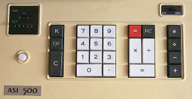
Descal ASI-500 Electronic Desktop Calculator
Updated 7/3/2021
This wonderful artifact is really quite unusual, a characteristic that makes it both intriguing, but at the same time, frustrating, because finding information about this machine is about as easy as finding a needle in a haystack. Some of the information in this exhibit is speculative simply due to the lack of information on this machine.The history of early electronic desktop calculating machines is difficult to document as it is. A number of factors contribute to the loss of much of the history of these machines, including the breakneck speed of electronic advancement during the late 1960's; the sheer number of companies that sprouted up to take advantage of the burgeoning marketplace, many of which went away as quickly as they came on the scene; the tendency of business to devote resources to developing the future rather than documenting the present and past; the need for companies to keep their trade secrets of the time secret; and perhaps also that computers seem to be a part of history that has garnered much more attention from historians. Along with that, many of the pioneers who were involved with the development of electronic desktop calculating machines, men like Dr. An Wang, have passed away, taking with them some of the historical tidbits of those times.
This particular calculator has yet another factor that makes it all the more difficult to document -- it was developed and manufactured in Japan by a company not really known for calculator technology. The problem with this is that while the company still exists today, so far, no one there that I've been able to get in touch with has any recollection of the company ever having been a competitor in the aggressive electronic calculator market of the late 1960's.
Identification Plate on Back Panel of the Descal ASI-500 The clues to the origin of the machine
weren't easy to find. Externally, there are no real good hints. There is a tag
on the back panel of the machine that says "DESCAL", along with "Series
TK 546"(a subtle hint), a serial number, power supply information, and
"Made in Japan". The keyboard panel has a tag that says "ASI 500", which
gives no further clue, except as a model designator. I've not come across
any advertising or even mention of DESCAL as a manufacturer or reseller of
calculators in the late '60's through mid-'70's. In order to find out
who made the machine, it required looking inside. After a significant
amount of time scrutinizing the innards of the calculator, the big clue
came. Etched into the component side of the CRT defection control/power
supply circuit board, buried under wiring for the CRT, is the text:
"TAKACHIHO KOHEKI CO. LTD.". A quick search with
Google finds that this
company still exists today! The company uses "TK" as an abbreviation for
their company name, a moniker that coincidentally fits with the "TK" Series
number listed on the tag on the back panel of the machine. I'm going to
use this "TK" acronym for the company's name in this exhibit (it's
much easier to type). A little more Web searching found an English version
of the TK's Web site. A click on the site's
"History"
link brings up a table of decades, beginning in the 1950's, with the
founding of the company in 1952. Sadly, there's no mention of the company's
foray into the calculator business. It appears that TK got its start
in business by importing electro-mechanical accounting machines made by
Burroughs into the Japanese market. Later, the company branched out into
its own businesses, including development of their own computer, data
communications, and other high-tech electronic and industrial enterprises,
and though undocumented, electronics calculator(s).
Profile View of the Descal ASI-500 It appears that "Descal" is a
registered trade name developed for sale of the calculators marketed by TK.
I had hoped that I would be able to find some references to Descal or TK in
old documents relating to early electronic calculators, but, alas, no luck.
The hope was that I could get an idea as to when TK got into the calculator
business, and if there were any other machines that they marketed. If anyone
out there has any more information about Takachiho Koheki Co., Ltd., or
calculators marketed under the trade name "Descal", please write me an
EMail. Any information that I can capture about this particular
segment of calculator history will help keep it from fading into oblivion.
I was able to find a US patent related to the design of display subsystem
of this calculator, which was applied for in Japan in March of 1969.
Date codes on parts inside the machine correspond with the 1969 time-frame.
So, it appears that, if the "ASI 500" was TK's first entry into the
calculator marketplace, this entry occurred sometime in 1969.
The particular example exhibited here has integrated circuits with date
codes from July/August of 1969. Another component has a date code
from early 1970, which indicates to me that the machine was likely made
sometime in the 1st quarter of 1970. The serial number of the machine is
9090205. If the serial number sequence started at 9090001, this would make
this calculator the 205th of this model built. If this assumption is
correct, this can be used to extrapolate that this model of machine likely
began production sometime in the mid-part of 1969.
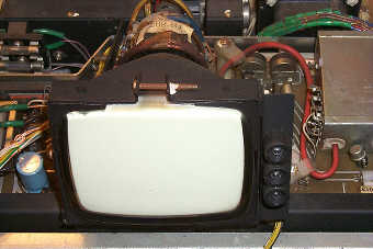
The CRT Display of the ASI-500 From a historical perspective, the ASI-500
is indeed interesting, but the machine is also interesting from a calculator
technology point of view. As far as has been found thus far, ASI-500 is
the only Japanese-made electronic calculator that uses a CRT display.
By the time this machine was marketed, most all
of its contemporaries (with exception of some Soviet-bloc made electronic
calculators) had abandoned the use of CRT displays in
favor of less-costly Nixie-tube, Burroughs Panaplex, Vacuum-Fluorescent,
or brand-new Light-Emitting Diode (LED) displays. The benefit of a
CRT-based display allows more information to be presented to the user
than a single-line numeric display. The CRT display provides the user
the benefit continuous display of the working registers of the
calculator, which helps the user keep track of the operations they are
performing as compared to a single-line display.
The disadvantage is that CRT displays are complex and costly to make.
The designers of the machine must have felt that presenting
the content of the working registers of the machine to the user may have
been beneficial in terms of accuracy, allowing the user to verify the operands
of the calculation being performed. While admirable, the additional cost
associated with the CRT display likely priced the ASI-500 out of the market
at the time that it was produced. Unfortunately, pricing information for
this machine has not been able to be found, so
it's difficult to state that the machine was significantly more expensive
than competitors' machines, but given the additional
complexity of the CRT-based display, it is likely a safe estimate that
the ASI-500 was at least a few hundred dollars more expensive than other
comparable machines of the time utilizing more conventional display technology.
CRT Tube Detail The Toshiba-made CRT uses a
long-persistence blue-white phosphor. The long-persistence phosphor is
used because the refresh rate of the display system is somewhat slow,
and if the phosphor didn't retain the image for a comparatively long time,
the display would flicker annoyingly. An artifact of the long-persistence
phosphor is that the digits seem to 'melt' into formation when changes
occur, as the image of the old digit at a given location persists for
perhaps 1/4 second before fading away, while the new digit at the location
takes its place. The display system in this calculator has some
non-linearity that causes some distortion
on the display as can be seen above, which is likely due to the fact that
the electronic components are approaching 50 years old and have aged. Due to
the apparent rarity of the ASI-500, in interest of leaving the machine as
original as possible, no components have been replaced.
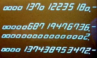
The CRT display presents four rows
of numbers to the user. The display is formed as vectors, "drawn" segment
at a time by deflection and modulation of the CRT's electron beam. Like an
another wonderful earlier CRT-display calculator, the
SCM Cogito 240SR, the Descal ASI-500
uses "half-height" zeroes. Other digits are rendered using a slightly
unconventional seven-segment digit representation. Sixes have a top bar, but
nines don't have the corresponding bottom bar. Sevens have an additional
segment and fours have a slight over-scan on the centerline.
Display Showing Negative Number Indications The four primary registers of the
machine are displayed at all times, except when the machine is
actually calculating, during which time the display is blanked.
Each of the register displays consists of 16 digits. Negative numbers
are displayed by a '-' displayed after the number, for example -5 would
display as '000000000005.0000-' (with the decimal point setting at four
digits behind the decimal point). The bottom row of numbers is the entry
and result register. As numbers are entered on the keyboard, they show
up in this register, and when calculations are completed, the answer is
displayed here. This register is displayed at a slightly higher intensity
level than the other registers to attract the user's eye to this
most-important register of the machine. The next register (moving up from
the bottom) shows the second number in a given math operation, with the
next register showing the first operand. The idea here is that the user can
see both of the operands and the result of math operations, which helps
insure accuracy as opposed to single register displays. Lastly, the top
line of the display shows the content of the memory register. In the
view of the display above, one can see that the memory register contains
-137,012,235,180 and the last calculation performed was -68,719,476,736 times
2, with a result of -137,438,953,472.
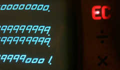
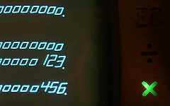
Overflow/Error Indication
Multiply and Divide Status Indicators Located to the right of the CRT
are three incandescent lamps that shine through colored jewels set
behind cutout nomenclature in the display bezel. These lamps provide
some additional status information to the user of the machine. The
top-most indicator, with a red "EC" nomenclature, indicates an error or
overflow condition. When the "EC" indicator is lit, the keyboard (with
exception of the [C] key) is ignored, forcing the user to press the [C]
key to clear the calculator and reset the error condition. The next
indicator is a green "÷" symbol, indicating that a division operation is
pending, and the bottom-most indicator is a green "X" symbol, which
lights to indicate a pending multiplication operation.
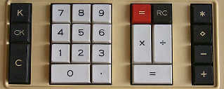
The keyboard of the Descal ASI-500 The Descal ASI-500 is a relatively
conventional calculator in terms of features. It provides a calculating
capacity of sixteen digits, and provides the standard four math
functions. The machine uses a mix of arithmetic and
algebraic math, with addition and subtraction operating arithmetically
(number followed by operation, e.g., 4 followed by [White =] will add
four to the result register), and multiplication and division operating
algebraicly (number, function, number, =). The machine performs the four
basic math functions, along with two-key squaring (enter number, press [X],
press [=]). The white [=] key serves a dual purpose, acting as an "add"
key, as well as serving to terminate multiplication and division functions.
The red [=] key performs the subtraction function, as well as allowing the
result of a multiplication or division to be negated when the red "=" key
is used to terminate a multiplication or division (e.g., 4 X 5 [Red =]
results in -20). The [RC] key swaps the content of the two operand registers.
A push-on, push-off [K] key
controls the constant function of the machine. When on, a constant is
enabled for multiplication and division. When the constant is enabled,
the "X" and "÷" indicators stay lit between calculations to show
which operation the constant operand applies to. The [CK] key clears
the entry/display register, allowing for correction of erroneous input,
and the [C] key clears the entire machine except for the memory register.
The ASI-500 has a full-function memory
accumulator register, with a group of keys on the right side of the keyboard
to control the memory functions. Memory functions include add[+], subtract[-],
recall[⋄], and recall and clear[*]. The memory [+] and [-] keys can
serve to terminate a pending math operation, causing the result of a
calculation to be accumulated into the memory
register. For example, with the memory register already containing
25, entering 2 X 6, then pressing the [+] key will result in 12. in the
result register, and 37. in the memory register. This functionality
is useful for sum of products types of operations.
Keyboard of ASI-500 and Burroughs C3550 - Note Similarities There are some interesting similarities
between the ASI-500 and another calculator in the museum, the
Burroughs C-3350. Given the relationship that
Takachiho Koheki had with Burroughs, it seems reasonable that TK may have
leveraged some of Burroughs'(actually, Sharp Corporation, as Burroughs was
an OEM customer of Sharp)technology for their calculator. The keyboard
assembly on the ASI-500 is very similar to that used in the
Burroughs C-3350 and other Burroughs(Sharp) calculators of similar vintage.
Some of the nomenclature is shared between the two machines; the indicator
used to indicate an error/overflow condition is labeled "EC" on both
machines. Along with the visual similarity, there are some logic
similarities that lead me to believe that perhaps the basic logic of
the calculator (with the exception of the display subsystem) was derived from
Sharp calculator designs. With the similarities between the ASI-500
and the Burroughs C-3350, one might think that the ASI-500 would provide
the "two-key" square root function of the C-3350 (enter number, press
[÷], press [=] to calculate square root), but alas, the ASI-500 does
not implement this functionality.
The decimal point logic of the ASI-500
uses an odd mixture of floating and fixed decimal modes that is very similar
to that used on the Burroughs C-3350. Even the nomenclature of the decimal
point selection switches is the same as used on the Burroughs C-3350 calculator.
Given all the similarities between the ASI-500 and some late '60's
Burroughs calculators, it seems likely that TK licensed
the basic design of the calculator logic from Sharp
designing their own CRT display subsystem to interface with the calculating
logic. Given that the patent found for the machine is mainly devoted
to details of the display subsystem, and no patent can be found regarding the
actual calculating logic, this seems to substantiate this assertion.
Decimal Point Setting Switches Two slide switches select the decimal
point location for the result and memory register. The "CDS" switch selects
(4 or 6 digits) the maximum number of digits behind the decimal point
that are displayed in the result register. Note that the setting is
the maximum number of digits behind the decimal point displayed in a result.
In some cases, fewer digits may be displayed. For example, with the CDS
switch set at "4", performing 17 X 1.25 will result in 20.25 on the display
(rather than the expected 20.2500). The calculator seems to suppress
insignificant trailing zeroes to maximize the capacity of the machine.
The setting of the CDS switch is not enforced for entry of numbers into the
machine. Any number of digits may be entered after the decimal point (within
the sixteen digit capacity of the machine), and, in the case of multiplication
and division, such a number will be preserved once it is transferred into
an operand register. However, once a calculation is completed, the result
is always forced into the number of digits behind the decimal point
as selected by the CDS switch (unless there are trailing zeroes which can
be eliminated as mentioned above). Any additional digits are simply
discarded.
The other decimal point selection switch,
labelled "MDS", selects the maximum number of digits behind the decimal
point in the memory accumulator register. This setting allows 0, 2, 4, 6, or 8
digits behind the decimal point. For example, performing the above
multiplication, then pressing the memory add [+] key to transfer the result
into the memory register, will also result in 20.25 being displayed in
the memory register, even if the MDS switch is set at 8 digits.
A switch located on the upper right
part of the keyboard panel controls the rounding of numbers transferred into
the memory register. This is unusual, in that the rounding function on
most calculators of the era tended to operate on the results of calculations
right after the solution to the problem is found.
The rounding mode switch has two positions labelled "5/4" and "OMIT". With
the switch in the 5/4 position, numbers to be entered into the memory register
are rounded up if the next significant digit is 5 or greater. The rounding
occurs before the number is transferred out of the result register when a
memory operation key is pressed, with the side-effect that the number in the
result register is also rounded per the setting of the rounding mode switch.
If the switch is in the OMIT position, any additional digits are simply
truncated before the memory operation takes place. An example of the
rounding function (with the memory rounding control switch at "5/4", CDS
set at 4, and MDS set at 4, performing 2 divided
by 3 and pressing the "=" key will result in "000000000000.6666"
showing in the result register. Performing the same calculation, but
finishing it by pressing the memory [+] key rather than the "=" key
results in "000000000000.6667" in the result register, as well as
"000000000000.6667" in the memory register (assuming the memory
register was cleared before the operation).
ASI-500 Keyboard Construction & Wiring The keyboard of the ASI-500 is made using
tried-and-true magnet and reed-switch construction. The keyboard mechanical
structure is almost identical to that used on the Burroughs C3550.
The numeric keypad has mechanical interlocks in it to prevent multiple digit
keys from being depressed at once, and this interlock mechanism is identical
to that used on the keyboard of the Burroughs machine. The keyboard assembly
is hardwired into the backplane wiring harness, which makes servicing the
machine a bit of a pain, because it is impossible to separate the keyboard from
the rest of the machine. Most calculators of the era use some form of
connector to allow the keyboard assembly to be removed and set aside, making
access to the rest of the electronics of the machine easier. My guess is
that this particular design-for-serviceability aspect was omitted on the
ASI-500 in the interest of cutting costs. The keyboard is modular, with
separate sections for each grouping of keys. The decimal point and round-off
slide switches, along with the power switch are mounted to the metal plate
that serves as the main structure of the keyboard assembly. The keyboard
assembly is secured to the upper part of the cabinet by a number of screws.
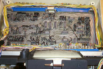
The Backplane Wiring of the Descal ASI-500 The backplane of the ASI-500 is a hand-wired
point-to-point affair. The wiring is painstakingly bundled, with branches
feeding the keyboard, power supply, indicator panel, and CRT display subsystem.
The backplane uses standard edge-connectors, with three plug-in slots for
the circuit boards of the machine to plug into.
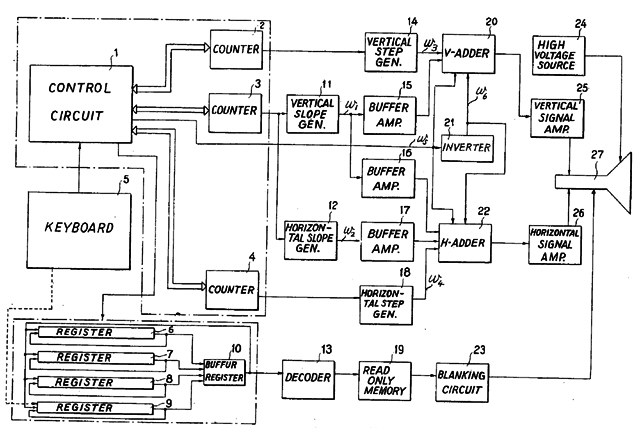
Block Diagram (from US Patent 3654612) of Display Subsystem Logic The guts of the machine
reside on three plug-in circuit boards which are stacked one atop another.
All of the circuit boards have metal frames around the outside edges of
the board to add structural rigidity. The top-most board is the CRT driver
board. This board contains the high-voltage power supply for the CRT, and
the deflection amplifiers and resistor networks (Digital to Analog
Converters) that interface the
logic of the display subsystem to the CRT. This circuit board is
quite primitively made, using a phenolic board with crudely-etched copper
traces on the back side of the board. It is apparent that a number of design
changes were made which involved doing kludges like cutting out sections of
trace and tacking components in line with the trace. Rather than revise
the circuit board artwork, the design changes were kludged in as part of the
manufacturing process.
A close-up view of the Hitach HD31xx and HD7xx IC's on one of the Circuit Boards of the ASI-500 Underneath the CRT drive board are
the two boards that contain all of the logic of the calculator. These
boards are much higher quality fiberglass-based circuit boards. The boards have
fairly high-density traces on both sides of the board, with plated-through
feed-throughs to connect both sides of the board. Gold-plated
edge-connector fingers are used for high-reliability interconnection with the
gold-plated pins on the edge connector sockets. These boards also have
"TAKACHIHO KOHEKI" etched into them, leading me to believe that the
fabrication of the calculator was done entirely in-house by TK. The logic of
the calculator is made up of small and medium-scale integrated circuit logic,
along with a lot of discrete diode/transistor logic. The IC's in the
calculator are all manufactured by Hitachi, with devices from their
second-generation
HD31xx-series
(in dual-inline packaging) and
first-generation HD7xx-series (in can-type packages) PMOS integrated circuit
families. Altogether 89 integrated circuit packages combine forces with
hundreds of diodes, transistors, resistors and capacitors to make up the
logic of the machine.
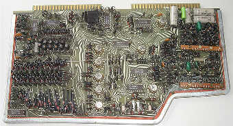
The bottom-most ASI-500 Circuit Board The bottom-most board in the stack is
larger than the other two boards, taking up almost the entire base of the
calculator. This board contains the majority of the ICs in the calculator,
with a total of 73 devices. The board contains the calculator registers,
arithmetic logic unit (utilizing a medium-scale HD3112 serial binary/BCD
adder/subtracter IC), and some of the display generation circuitry,
including a diode-based read-only memory (ROM) (center of circuit board)
that forms the character generator for the CRT display.
This ROM is made of a series of diodes that define the on or off state of
each segment that makes up a display digit.
The Middle Logic Board
Sandwiched between the large logic
board and the CRT drive board is a smaller circuit board that contains
a large amount of discrete component logic, and only 16 integrated
circuits. This board appears to contain
keyboard encoding, some of the display generation timing
logic, the master clock circuitry, and general control logic.
Mysterious Component Strips on Middle Logic Board of Descal ASI-500 At the
lower right corner of this board there are two strange strips of circuit board
material each of which with what looks like four little stacks of metal
washers on small posts. Into each arrangement of these stacks, three
electrical connections are made. I have not been able to figure out what
function this structure performs. If you have any idea what these might
be, I'd love to hear from you.
Power Supply of the ASI-500 The power supply of the ASI-500
is a work of art. Electronically the power supply is of a standard linear
design, with a fairly large multi-tapped transformer stepping down the
AC line voltage to a number of lower AC voltages, which are then rectified
and filtered, then regulated to the appropriate clean DC voltages required
by the circuitry of the machine. The power supply is modular, in its own
assembly across the back of the machine. The power supply is built to nearly
military specifications, with a heavy machined metal chassis, and truly
massive heat-sinks, with a small (but noisy) fan integrated into the
assembly to cool the power supply regulation transistors. The heat-sinks
and fan are all enclosed in a housing that serves as a
tunnel to direct the moving air from the fan across the heat-sinks, and
out vents along the sides of the machine.
The power supply, like all of the other electronic assemblies in the machine,
is hard-wired into the wiring harness, rather mitigating the modular design
of the machine. The upper part of the cabinet of the calculator is made in
two pieces, with the main section covering the majority of the calculator, and
a small back section that is separately removable to allow access to the
power supply fuses without having to take the entire cabinet apart.
Like many calculators from the early
IC era, this machine has a few operational quirks. Division operations will
overflow if the most significant digit of the dividend is non-zero.
For example, 123456789012.1234 as the dividend will cause an overflow as
soon as the divide key is pressed, while 023456789012.1234 will not. Also,
the circuitry to detect division by zero isn't completely robust,
only detecting zero without a decimal. For example, if you enter a number,
press divide, then press any number of zeroes (or just hit the equal key
right away), the machine properly detects the divide by zero condition,
lighting the "EC" indicator and locking out the keyboard. However, if you
enter a number, press divide, then enter 0.0 as the divisor and press the
[=] key, the machine will go off into space, not realizing that it has been
commanded to perform an impossible operation. The display blanks and stays
that way until the [C] key is pressed to reset the machine.
The ASI-500 is not a very fast calculator.
I believe that part of this is related to the fact that the display subsystem
runs rather slowly, which pretty much puts a limit on the speed of the rest
of the calculator. In doing some research on various CRT-based display
systems for use in calculators, I ran across a patent that lists a 'two speed'
calculator, where the logic runs at a slow speed when idle to generate
the CRT display, and shifts into "high gear" when doing calculations (while
the CRT is blanked) to speed up the operation of the machine. A great idea,
but one that apparently was not implemented within the logic of this machine.
The standard 'all nines' division benchmark can not be performed to the
full capacity of the machine due to the division quirk mentioned above.
However, 099999999999.9999 (15 nines, with decimal point setting at 4) divided
by 1 takes just over 0.9 seconds, while 9999999 X 9999999 takes nearly
1/2 second.