
| +Home | Museum | Wanted | Specs | Previous | Next |
Monroe 1665 Desktop Programmable Calculator
This calculator came to the museum through the generosity of Janet Harrison of Birmingham, Alabama. This machine was originally owned by her father, Thomas J. Harrison(1914-1996), who was an engineer that specialized in metallurgy specific to large-scale industrial and construction use of metals. Thomas received a degree in mechanical engineering from the University of Alabama in 1938, and ended up going to work as a sales engineer for Republic Steel, then later Fox Steel. Later, he started his own business serving as a manufacturers rep. for a number of steel producers. The Monroe 1665, along with a Wang 720C, were used by Mr. Harrison for performing the various complex mathematical functions relating to structural analysis, metals properties, and other aspects of his business. Mr. Harrison kept these machines as prized possessions, treating them with great care. After Thomas, and later, his wife, passed away, his family looked to find a place where these machines would be preserved with the same reverence and respect that Thomas gave them. Fortunately, Janet found the Old Calculator Web Museum, and after a family meeting, Janet and other members of her family decided that these machines would find a new and permanent home here in the museum.

The "Brag Tag" on the front panel of the Monroe 1665.
This great old machine is an example of Monroe's first-generation of printing desktop programmable calculators. Monroe debuted the 1600-series of calculators sometime in the early part of 1970. The 1665 may look similar to another machine in the museum, the Monroe 1860, but the 1860, while visually similar, is am example of the second generation of calculators that were designed by Computer Design Corporation for Monroe. Computer Design Corporation had all of the electronic design expertise that Monroe needed when electronic circuits squeezed mechanical technology out of the desktop calculating scene, making for a perfect partnership. Computer Design Corporation developed the electronics, and Monroe leveraged their large and experienced sales and service force to sell and maintain the calculators.
The 1665 is the printing version of the Monroe 1655 Nixie-tube display calculator. Functionally, the two machines are almost identical, with the main exception being that the 1665 provides a thumb-wheel setting for selection of decimal point position, versus floating decimal logic for the 1655. From a construction point of view, the 1665 uses a more modular design, taking up more desk space, but using a generalized backplane-based architecture than the somewhat more monolithic design of the 1655. Both the 1655 and 1665 were targeted toward the scientific and engineering user communities, with an extensive assortment of scientific functions built in.
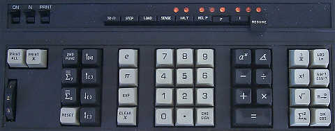
Detail of the 1665's Keyboard
The 1665 is quite a capable machine for the early 1970's. The calculator boasts a wealth of mathematical functions including trig, logarithms, roots and powers, and factorials. Along with the higher-level math functions, the calculator is fully programmable, allowing rather complex programs to be written to perform just about any kind of mathematical calculation that can be expressed within the 128-step (or optionally, 256-step) program memory of the machine. As with most of the machines in the first generation of Compucorp/Monroe calculators, the 1665 has a total of ten memory registers, numbered zero through nine. Registers 7, 8, and 9 are general purpose registers used by some of the math functions of the machine, leaving registers 0 through 6 for more general user needs. Since the calculator uses IC-based Random Access Memory (RAM) that is volatile (the content of memory is lost when the machine is powered off) for program storage, the calculator has the ability to allow an optional external punched card reader (the CR-1 Card Reader) to be connected to allow for easy loading of programs into the memory of the calculator from punched cards.
Like the other first-generation of Compucorp-designed calculators, the Monroe 1665 uses Compucorp's "HTL" chip set. The HTL chip set is a comprehensive set of complex Large Scale integrated circuits that are designed in a modular fashion to allow varying combinations of the chips to make up a wide range of calculators with different capabilities. The HTL chip set was really a wonder of the times, essentially a multi-chip implementation of a microcoded 8-bit microprocessor, quite a number of years before the microprocessor became a reality. In the case of the 1665, a total of 28 of the AMI-made (AMI served as the fabricator for Computer Design Corporation's HTL chip designs) HTL chips combine forces to make up the logic of the Monroe 1665. Along with the HTL-labelled parts, there are eight other chips that are not labeled as HTL parts, are also made by AMI, and appear to be mask-programmed ROM chips. These ROM's contain the microcode that implements the functionality of the calculator and directs the operation of the HTL chip set.
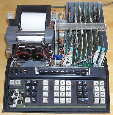
Inside the Monroe 1665
The 1665 is built in a modular fashion, with four main components. The printer, power supply, keyboard assembly, and the logic. The logic of the machine consists seven logic boards that plug into a printed-circuit backplane. Each logic circuit board is made out of high-quality fiberglass board material, with plated through holes to connect the two sides of the board. Each board has edge fingers across the bottom of the board that plug into a connector in the backplane. The function of each of the circuit boards is conveniently etched on each board. At the left end of the card cage, a small board contains voltage regulation circuitry for the power supply. To the right of this power supply board, the remaining seven boards make up the logic of the machine. The logic boards, left to right in the chassis as shown above, are: Printer Drive, Data Memory, Program Memory, Control, Compiler/Flags, LEMP, and (the optional) CLEMP.
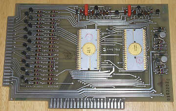
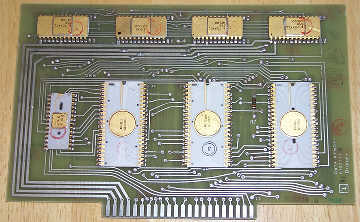
The Printer Drive (left) and Data Memory (right) Circuit Boards
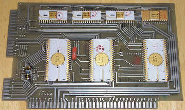
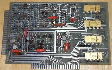
The LEMP (left) and CLEMP (right) Circuit Boards
Some of the boards' functions are fairly obvious from their names, but a few require some explanation. The Printer Drive board contains HTL03 and HTL14 chips, along with transistorized driver circuitry for the printer's solenoid-activated print hammers. The HTL03 and HTL14 chips combine forces to take the timing signals from the printer, as well as the data from other HTL chips that represents what is to be printed, and generates the necessary timing signals to fire the print hammers to print out the data, as well as controlling the ribbon color selection (black or red) and advancing the paper. The Data Memory board contains the RAM (Random Access Memory) where the memory and other working registers of the calculator reside. Along with the four HTL00 Dynamic RAM chips, the remaining IC's (HTL04, HTL05, HTL06 and HTL10) handle the addressing and refresh of the memory.
The LEMP board contains the functions that relate to the programmable capabilities of the calculator, including the RAM (made up of four HTL00 DRAM [Dynamic RAM] chips) for the base 128-step program memory, and additional logic (HTL15, HTL16, and HTL17 chips) for refreshing the RAM, and decoding the various programming functions, along with the calculator's keyboard interface. LEMP, by the way, is a Compucorp-coined acronym for "LEarn Mode Programmer". The optional CLEMP (with the C standing for "Card") board provides expansion memory (again, four HTL00 DRAM chips) for increasing the number of program steps from 128 to 256, as well as providing the interface for the external punched card reader.
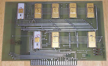
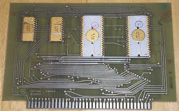
The Program Memory (left) and Control (right) Circuit Boards
The Program Memory board's name is a bit misleading. It isn't where the program steps are stored (program steps are stored on the LEMP and CLEMP boards), but rather, it contains the overall ROM microcode program that operates the calculator as well as the the addressing logic for the microcode ROM which is performed by the HTL02 and HTL12 chips. The six ROM chips on the Program Memory board hold the low-level instructions that govern the entire operation of the calculator.
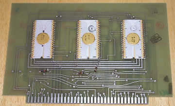
The Compiler/Flags Circuit Board
The Control and Compiler/Flags boards combine to form the director of the whole operation. he Compiler/Flags board (containing HTL09, HTL11, and HTL13 chips) accepts key-codes and program instructions from various other sections of the calculator, and dispatches various functions to the Control board (with HTL07 and HTL08 chips) to cause the various operations to be executed in accordance with the microcode. Both the Compiler/Flags board and the Control board have their own small areas of ROM associated with them, as well as the main microprogram ROM on the Program Data board.
Moving into the other areas of the machine, the keyboard of the 1665 is a modular design, with sealed reed-switch modules providing the key mechanisms. The key modules are soldered into a circuit board, which contains some simple discrete component- based logic for encoding the keyboard functions. The keyboard has a wiring harness that terminates in an edge connector socket that plugs into the LEMP board.
Printout from the Monroe 1665
The printer used in the 1665 is
a Seiko-made device, a variant of the famous Shinshu Seiki Co. (later EPSON)
EP- 101 printer developed
out of technology developed for use in timing devices made by
Seiki for the 1964 World Summer Olympic games held in Tokyo, Japan. The
printer is a hammer and
drum type impact printer that can print 21 columns (though
19 columns are used by the 1665 calculator), and can print
at 2 1/2 lines per second. The printer has a two-color ribbon
that allows negative numbers to be printed in red. Numeric output is
formatted with ten significant digits plus sign. When scientific notation
numbers are printed, ten significant digits plus sign make up the mantissa, and
two digits plus sign make up the exponent. The 1665 has a capacity
of thirteen digits maximum, along with an extra guard digit, however only
ten significant digits are printed. The printer has a number of
alphanumeric characters that are used to indicate error and overflow
conditions by spelling them out, i.e. printing ERROR when an invalid
operation is performed, and OVERFLOW when the capacity of the machine
is exceeded. As with all drum and hammer printers, this printer is a bit
noisy, with the hammer impacts and the thunk of the paper
advance solenoid combining to make what can be a distracting noise. When the
printer is idle, it only emits a soft whirring noise which isn't obtrusive.
Like all of the Compucorp-designed
calculating machines from this era, the 1665 uses the rather unusual
[2ND FUNC] key that provides the result for the secondary function on
keys with two functions listed on them. When pressed after the
function key is pressed, the [2ND FUNC] key recalls the content of memory
register 9. When one of the dual-function keys is pressed, both functions
on the key are calculated at the same time, with the primary function's
result printed, and the secondary function's result stored in memory register
9, immediately recallable by pressing the [2ND FUNC] key.
So, for example, to calculate the cosine of 60 degrees, one would key
in "60", then press the dual-function key labeled [SIN/COS]
(resulting in the sine of 60 degrees being printed and the cosine of 60 degrees
being stored in memory register 9 (overwriting any previous content there),
followed by the [2ND FUNC] key, which would print the result of the cosine
calculation by printing out the content of memory register 9.
The 1665 is very much a general-purpose
calculator. The selection of math functions, combined with its programmability
makes it equally applicable for scientific, statistical, financial, and
engineering use, although Monroe's marketing literature targets the machine
specifically for engineering use. Included in the repertoire of functions
available from the keyboard are: Trigonometric functions (sin, cosine, arcsine,
arc-cosine); factorial; square root; power function (ax); natural
and base 10 logarithm; radians to degree conversion; reciprocal; rectangular
to polar conversion, and one key recall of the constants e and π
Additionally, a summing function key provides automatic accumulation
of item count, sum of numbers, and sum of squares for statistical calculations.
There are a number of keys that
control access to the calculator's ten memory registers. The
[↑[ ]] key recalls the content of the memory register
specified by the following key-press (0-9). The [↓[ ]]
key stores the current content of the working register into the memory
register specified by the following digit key-press. The
[↕[ ]] key exchanges the working register
with the memory register specified by the following numeric keypress. The
[=Σ 7] key adds the content of the working register to
register 7, and likewise, the [=Σ 8] key does the same
thing, but adds to register 8.
Rounding out the complement of functions
available from the keyboard are basic operational keys, including
the [RESET] key, which serves as a "clear all" function. The [CHG SIGN]
key toggles the sign of the number being entered. The [EXP] key shifts
the calculator into exponential entry mode, allowing entry of the exponential
part of a number in scientific notation. The [CLR x] key clears
the content of the numeric entry register, allowing correction of
erroneously entered data. The [PRINT x[ key prints the current
content of the working register, mostly used in programs to print
out results of calculations. The [PRINT ALL] key causes the content
of the working register, followed by the content of each of the memory
registers, to be printed. Pressing this key results in a machine gun-like
rattling of the printer as the numbers spew forth on the printout.
A group of three paddle switches control the power, printing format (standard
or forced scientific notation), and whether the calculator printer prints
all transactions, or only results.
Unlike its Nixie-display counterpart
the 1665 is a fixed decimal point machine. A thumb-wheel at the left hand
side of the keyboard selects the number of digits in front of the
decimal point. This is rather unusual, as most fixed-decimal point
calculators allow the user to specify the number of digits behind
the decimal point rather than those in front of the decimal point. What
this curious method allows, however, is the calculator to always try to
give the most precise answer possible, maximizing the number of digits
behind the decimal point, while preserving the most significant digits
that the user selects.
The Programming Control Panel for the Monroe 1665
A comprehensive programming environment
allows the 1665 to perform a wide range of calculations. As with most
programmable calculators of the time, the calculator is 'learn mode'
programmable, meaning that the calculator is put into a learning mode,
where keyboard presses are converted into program codes and stored into
program memory, step at a time. A special set of keys and indicators
located above the main keyboard provide access to the programming functions
of the machine. Depressing the push-on/push-off [LOAD] key activates
learn mode, causing keyboard key-presses to be stored into program memory.
The [P] and [I] keys select the function of the 8-bit neon-lamp display
for indicating the content of the program counter (P) or instruction code (I).
When the [P] key is depressed, the display shows the current content of the
program counter, which advances one step for each key-press stored into
program memory. When the [I] key is depressed, the display instead shows
the 8-bit key-code of the key that is stored into memory. The [TO()] key
is used to enter jump instructions...pressing the key followed by a
single key-press selects a destination address for a jump. The [HALT] key
enters a halt instruction into memory, used to stop the program to allow
the user to enter data manually. The [RESUME] key begins or restarts
execution of a program at the current position of the program
counter when pressed. The push-on/push-off [STEP] switch puts the
calculator into single-step mode, causing execution of one instruction
each time the [RESUME] switch is pressed. The [SENSE] switch is a
push-on/push-off key that a program can test the status of, allowing
the program to take different action depending on the state of the switch.
Lastly, the [RCL P] switch enters an instruction that jumps to the content
of the program counter just after execution of the last TO() instruction.
This function is used for providing a simple subroutine capability.
Base program memory on the 1665 is 128 steps, but the calculator (with
addition of the CLEMP board) is expandable to 256 steps of program memory.
One weakness of this series of calculators is the inability to make
a record of a program in memory. Later Compucorp-designed calculators
using the "ACL" chip set (such as the Monroe 1860) provided a means
to print a listing of the program out on the printer.
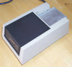
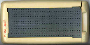
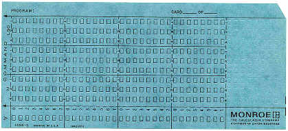
An Unused Monroe Punched Card for use with the CR-1 Card Reader
Along with its learn-mode programming capabilities, the 1665 can be
connected (via a female DB-25 connector on the rear panel of the calculator) to the optional model CR-1
card reader to allow programs to be loaded from punched cards. The
pre-scored punched cards can each hold up to 32 steps, requiring that larger programs be stored on
multiple cards. Cards are are fed into the card reader sequentially, one at a time, with the short edge containing the
first colunm fed into the reader. A small motor draws the cards through the reader when the card is
gently pushed into the feeder slot on the reader. Once the
card is inserted sufficiently, the card is drawn through the reader by the motor and read a column at a time. The card
exits the reader at the rear. The CR-1 uses an optical system using a light source and ten photo-transistors, one for
each row on the card. As the columns pass under the light source, the presense of a hole allows the light to shine
through and turn on the photo-transistor, while the lack of a hole will leave the photo-transistor off, thus providing signals
that the calculator converts into data. The reader stores the 9-bit instructions sequentially in the calculator's program memory
at a step address pre-entered into the calculator prior to beginning feeding the cards in.
With the extra 9th bit available on the punched cards, additional instructions are available that aren't
accessible through the keyboard. Some of the extended instructions are somewhat specific to each model of calculator, and
are documented in the Advanced Programming manual for each model.
The CR-1 Punched Card Reader Nine rows are used to represent
the 9-bit program operation code. One row is used as a validation row. This
row must have a punch in it to make the operation code in the column
valid. Columns without this validation row punched are skipped over by the calculator.
Monroe sold packs of small adhesive patches that could be carefully affixed over holes that were incorrectly punched in order to
correct mistaken punches.
The Monroe "Port-A-Punch" Fixture for Punching the Cards Cards can be punched with a pencil point
or other pointed object, or, via the use of the "Port-A-Punch", an accessory
fixture into which a card is placed, making it much easier to punch
cards, while catching the 'punches' (chad) so they don't end up all over the place.
The Port-A-Punch comes with a stylus to allow for easier punching of
the cards. A transparent plastic overlay with small holes for the stylus
to poke through is removed, a card slid into the Port-A-Punch, and then
the plastic overlay slid in on top of the card. The card is then punched,
and when complete, the card is slid out, ready to place into the CR-1
to be read into the calculator. The "Port-A-Punch" card punching fixture
was actually invented by IBM and was licensed by a number of manufacturers
including Wang Laboratories and Compucorp/Monroe.
Via punched card programming, it is possible to access additional
math capabilities of the calculator. Included are functions such as
ex, extract integer portion, direct branching, special conditional
operations, shift operations, as well as access to special routines
in the calculators microcode that allow low-level manipulation of the
calculator's hardware.
The 1665 calculates at a rate
in line with the other calculators based on the HTL chip set, with most
operations completing within a few tens of milliseconds. Some of the
more complex operations, such as the ax and
x! (factorial) functions can take up to three seconds to generate
a result. Programming functions aren't executed terribly fast, with 256 steps of
"CLEAR x" instructions taking six seconds (with the printer
turned off), or about 42 steps per second. A simple program that loops, adding
1 to the working register, runs at about 2 1/3rd loops per second.


Click on image for a larger view
