
| +Home | Museum | Wanted | Specs | Previous | Next |

Commodore US*1M Calculator
The Commodore US*1M is a follow-on calculator to the Commodore US*1, adding basic accumulating memory register functionality. Other than the rearrangement of the keys on the keyboard (using the same keyboard design), and a slight difference in the display module, the US*1M visually looks just like the US*1. The cabinet components are identical. However, while externally similar, the US*1M is quite diferent internally. The general mechanical layout inside is similar, with the same monolithic spring-contract keyboard module used in both machines that connects to the main board with wire jumpers, along with a planar gas-discharge display module. The real difference comes in the logic of the machines. The US*1 uses a single-chip calculator IC made by General Instrument. The US*1M uses a two-chip chipset made by (at the time) relative newcomer to calculator chip marketplace, Western Digital. The General Instrumnet(Pico Electronics) chip used in the US*1 is a single 24-pin IC, while the Western Digital chipset used in the US*1M takes up quite a bit more room on the circuit board, using two 40-pin packages. The only real difference between the two calculators is the addition of the memory register, which wouldn't really account for the significantly larger amount of real-estate taken up by the Western Digital chipset. The real difference is that altough the Western Digital chipset uses a sophisticated microcoded architecture similar to that of the General Instrument chip, the layout of the ICs is more conservative than the GI chip, and the general design requires more interconnections between the two chips, requiring the larger 40-pin packages. The Western Digital chipset also integrates the digit drivers into the chip, while the General Instrument chip required external transistorized digit drivers. to the chipset having its own drivers for each position on the display, where the General Instrument C-500 chip in the US*1 requires external transistorized digit drivers. The Western Digital chipset still requires external transistor drivers for the seven segments and decimal point. Both the C-500 chip and the Western Digital chipset require external clock generation and power-on reset circuitry.
The US*1M was introduced in the latter part of 1973, about eight to ten months after the US*1 was introduced. It is interesting that despite the machine being designed later than the US*1, it uses IC technology that is a bit behind the curve as compared to the US*1. The General Instrument chip in the US*1 was quite sophisiticated for its time, packing all of the function of a basic four-function calculator into a single 24 pin package. The US*1M only adds the memory functionality to the features, yet takes two 40-pin integrated circuits. Adding a basic accumulating memory function to an electronic calculator involves adding a register to contain the content of the memory, which, in the case of an eight-digit calculator, would conservatively consist of a shift register containing 40 bits. The 40 bits would be composed of 32 bits for the number in the register (eight digits with four bits per digit), and eight more non-displayed bits (two digits worth) to store the decimal point position of the number and its sign. Also required would be gating to select the memory register as the recipient of data from the arithmetic unit (along with the other registers), as well as selecting the memory register for input to the arithmetic unit, as well as additional sequencing logic to direct the steps through the process of adding the memory regsiter to the display register, copying the content of the memory register to the display as well as clearing the memory register. This is not a very complex addition, but I suspect that Western Digital's experience with Large Scale MOS calculator IC design at this stage was fairly limited, and they were very conservative in their IC designs, which led to the need for two ICs with a significant number of interconnects between them, thus the 40-pin packages. The US*1M provides the basic four math functions, and provides a constant all four functions, which is an unusual feature, even today. Most electronic calculators provide a constant only for multiplication and division. The US*1M uses algebraic logic, which is also rather uncommon in calculators of this time, with a separate [=] key used to calculate the result of an operation. The calculator provides a fully-floating decimal, with the decimal point always positioned to provide the maximum amount of accuracy within the eight-digit display capacity of the machine.
Inside the Commodore US*1M
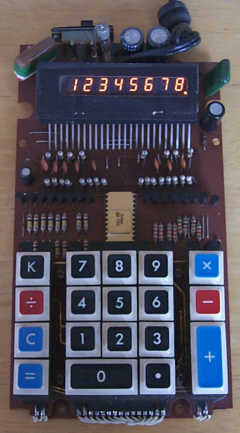
Internally, the machine is quite simple, utilizing a single-chip calculator LSI (Large Scale Integration) IC for the brains of the machine, a General Instrument C-500. General Instrument was not known as a major manufacturer of calculator IC's, making this machine rather unique, although the same chip was used in the Litton Royal Digital VIII-K calculator, which was marketed at around the same timeframe as the Commodore US*1M. The C-500 chip in the Commodore US*1M is plugged into a Molex-style strip socket, which seems unusual for a low-cost calculator, as normally the LSI's were simply soldered into the board. This makes the chip easily replaceable if there were to be some kind of problem that developed with the chip - a nice serviceability feature. The remainder of the circuitry makes up power supply and display drive circuitry. The planar display is driven with discrete transistor drivers. All of the circuitry of the machine, with exception of the keyboard module itself, is contained on a single printed circuit board. The circuit board is made of a phenolic material, with circuit traces only on the back side of the board.

Odd Display Behavior When Calculator is Told to Divide by Zero
The US*1M uses a planar gas-discharge display, similar in design to a Burroughs Panaplex panel, but the display is not manufactured by Burroughs. The display uses the standard seven-segment digit arrangement, with a right-hand decimal point included with each digit.
The US*1M exhibited here was built sometime in the 2nd quarter of 1973, based on the date code on the LSI. The calculator is typical in speed for single-chip calculators of this time, with all nine's divided by one taking about 1/3 of a second to complete. The display is not blanked during calculation, and flickers about a bit while calculations are occurring.
As mentioned above, the US*1M offers a constant function on all four math functions. The [K] key is used to set the constant and the type of operation to be performed. For example, to set a constant addition of 1 (turning the calculator into a counter), the user simply presses [1] followed by the [+] key, followed by the [K] key. Then, each successive press of the [=] key will cause the number in the display to be incremented by 1. Similarly, constant multiplication by two would be done by pressing [2], then [X], followed by the [K] key. Once constant operation is set, the only way to clear constant mode is to press the [C] key, clearing the machine and the constant.

Keyboard Detail
The keyboard of the US*1M uses spring-type contacts. The keyboard is a separate module, wired to the main circuit board with individual wires. The keycaps are made of plastic, with molded in color and nomenclature. The US*1M opts for a rather patriotic (given the US designation) color scheme for the keyboard, with blue, red, and black background on white keycaps, and white nomenclature.
The US*1M forgoes any form of overflow or error detection -- any results in excess of the capacity of the machine are simply discarded. The machine does seem to keep track of decimal point locations up to another 8 digits beyond the end of the display. For example, performing 99999999 X 99999999 results in 99999998, with no decimal point lit. Following this calculation with a division by 10000000 results in 999999998., indicating that the decimal point position was kept track of, even though it was not visible on the display. The US*1M has no input overflow detection, simply ignoring any input in excess of eight digits.

Closer View of General Instrument C-500 LSI and Display Driver Circuitry
The US*1M displays negative numbers by lighting a "-" on the digit preceding the most significant digit in the result. A side-effect of this choice of display method for negative numbers is that the largest negative number that the machine can accurately represent is -9999999, losing a digit of display to the '-' sign.
Performing division by zero on this machine causes an interesting counting effect, with the least-significant digit counting very quickly such that it looks like an 8, with some of the segments flickering ever-so-slightly, and the third digit from the right counting where it's easy to recognize the digits as they count off. All of the decimal points light up, and the digits that aren't counting show digits that somewhat relate to the divisor. The only way to exit this state is to press the [C] key to clear the calculator, or to power it off, wait a few seconds, then power it back on again. A static example of this behavior is shown in the image of the display above.