| +Home | Museum | Wanted | Specs | Previous | Next |
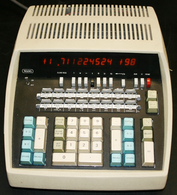
Wang 462 Statistical Programmable Calculator
Updated 8/19/2018
Thanks to the generous donation by a kind fan of the Old Calculator Museum, and to Dennis McNurland for donation of a supply of Wang 400-Series parts, the museum is happy to exhibit the Wang 462 calculator. The 400-Series calculators were the last of Wang's stored-program programmable calculators, further capitalizing on advances in integrated circuit technology and architecture debuted in the Wang 600-Series calculators (though the Wang 600 couldn't benefit from the size reduction due to the use of the wire-rope microcode ROM of the earlier 700 and 500-series machines, which fixed the footprint to be the same as these earlier machines) to reduce the size of the 400-series calculator to a much smaller package, while preserving only a slightly scaled down version of the functionality of the 600-Series. The 400-Series, introduced likely sometime in mid- to late-1972, gave Wang a definite edge over arch-rival HP in terms of the amount of desk space occupied by an advanced programmable calculator. (See exhibit on the HP 9810, though Compucorp/Monroe had small-footprint programmable "customizable" desktop calculators on the market for over a year before the 400-Series were introduced.
The 400-Series machines were followed-up by Wang's last line of calculators, the C-Series (an example being the Wang C-52 Advanced Scientific Calculator), that took advantage of much of the same packaging and technology of the 400-Series machines, but eliminated the programming functionality. It appears that early-on, the C-Series were known internally to Wang as the "400L" (perhaps L being for "Light"), as some Wang documentation in the museum's possession refer to circuit boards in the C-52 calculator as having the "400L" designation, and others, sharing the same motherboard designs, using the C-Series designation. The Model 462-0 exhibited is definitely a true 400-Series machine rather than one of the "400L/C-Series" calculators, though it looks similar to C-Series calculators visually).

Wang 462 with top cabinet removed
Like almost all of Wang's calculators, the Model 400-Series calculators consisted of a line of machines, with a number of different models, each catering to a specific mathematical discipline or capabilities. The 400-Series included four known models; the 450 Basic Scientific, the 452 Advanced Scientific, the 462 Statistical, and the 487 Surveying calculator. Initially, it appears that all of the 400-Series calculators were introduced with 320 steps of program memory, but somewhere after introduction, a change was made providing the base calculator (Option -0) with 64 program steps, and an option (option -1) that upgraded the program step memory to 320 steps. After this change was made, the base model units were sold with a "-0" suffix after the model number, indicating that the machines had a program memory capacity of 64 steps. Machines with a "-1" suffix on the model number included an extra 256 steps of program storage, which expanded the available program space to 320 steps. 400-series calculators produced before the expanded memory option was available had just the model number on the tag, with no "-" designation after it. The machine exhibited here is a model 462-0, with the base 64 steps of program memory.
The 400-Series machines all share a completely common architecture, with a "personality" board containing ROM code that provide the specific functions offered by the machine, for example, in the 462, the ROMs on the personality board contain the programs for the 462's advanced statistical functions. In the Model 452 Advanced Scientific, the ROMs on the personality board contain programs to carry out a different set of mathematical operations more suited to scientific and engineering applications. The programs on the personality board are coded as if they were "learn mode" programs, not in direct microcode as found on the motherboard. The main operating microcode of the machines in all of the 400-Series is identical, and contained in eight ROM chips located on the motherboard. The main microcode ROMs contain the low-level operating instructions that give the machine its basic functional and math capabilities. The personality board adds in the advanced model-specific functionality.
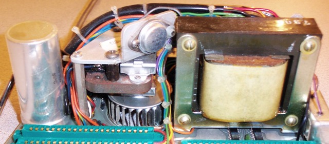
Wang 400-Series Power Supply Detail
The 400-series and C-series calculators share a common general architecture and mechanical packaging. The calculators in both lines share basic structural, cabinet and power supply design, keyboard construction, and display subsystem. This design is based on a motherboard/daughterboard arrangement, with the motherboard situated in the bottom of the chassis. The motherboard contains the power supply (commonly-used linear transistor-regulated circuitry), power-on startup and initialization circuitry, microcode ROM address decoding, and the common operating microcode (shared by all of the machines in the 400-series). The common microcode for the 400-Series calculators is stored in eight 512x10 Mask-Programmed ROMs (manufactured by Electronics Arrays for Wang) plugged into IC sockets on the motherboard. The ROM microcode is addressed 40 bits at a time (the size of the microcode word in the 400-Series). There are two banks of 512 microcode words (for a total of 1024 microcode words). The motherboard in the 400-series machines has very little active circuitry on it, with a total of six integrated circuits (not including the eight ROMS) for ROM address decoding, buffering, and power-on-reset. The 400L/C-Series calculators have a much more complex motherboard with all of the microcode ROM and address decoding, microcode sequencing, and other miscellaneous logic. There are only two slots for a plug-in boards, consisting of a slot for a combination personality ROM and RAM board, and the Arithmetic Logic Unit. Another difference between the 400-Series and 400L/C-Series calculators is the addition of a small vertically mounted squirrel-cage fan mounted in the power supply area to help keep the more complex circuitry of the 400-series machines cool. This fan makes the 400-Series machines noticeably noisier, as well as slightly taller (because of the fan) than the C-Series machines, which are convection-cooled. The 400-Series calculator definitely runs hot, even with the fan to help cooling.
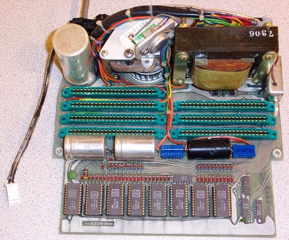
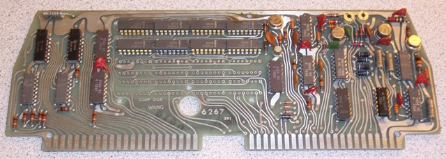
Wang 462 Motherboard (Board 6029)
The common microcode ROMs for the 400-Series carry Wang Part Numbers 377-0039 through 377-0046. These ROM chips are custom mask-programmed devices, meaning that the data stored within them is designed into the photographic masking used to create the integrated circuit chip, and thus the code is a permanent part of the chip. Wang Laboratories engineers developed the microcode through the use the company's IBM 360/65 mainframe computer that ran a program that simulated the circuitry of basic 400-series calculator architecture. With the simulation of the calculator running on the mainframe, microcode could be submitted to the simulator, and "run" as if it were running on the real hardware (though significantly slower). The simulator had means by which the operator could step through the microcode, monitoring the status of the various functional units of the machine, to develop and debug the microcode before the hardware actually existed. The notion of using a mainframe-based computer program to simulate the behavioral functions of the electronics of a calculator began with the Wang 700-Series calculators, when it was realized during development of the machines that the complexity of the logic, and the lack (at the time of the 700-Series development) of integrated circuit ROM technology made it much more difficult to develop and test the incredibly complex microcode. The realization of a simulator running on a computer made the whole process much more streamlined, efficient, and less prone to error.
Once the microcode was running properly on the simulated calculator, the microcode data was translated onto specially-formatted punched cards that were delivered to Electronic Arrays. Electronic Arrays would use the data on the punched cards to create a custom photo mask for the ROM that encodes the various 1's and 0's that make up the microcode. The cards were read by a computer which generated a magnetic tape that drove a photoplotter that would produce the photomask artwork based on the data on the cards. The photomask contains light and dark areas on large sheets of photographic film that was photo-reduced to expose the uppermost layers of the integrated circuit to create (or not create) electrical connections at various points in the circuitry to embed an image of zeroes and ones corresponded to the data on the punched cards. This mask was then used during the process of building the IC to encode the data content permanently into the circuitry of the ROM. Once a ROM was fabricated, there was no way to change its content, meaning that if there was an error in the microcode, the whole batch of ROMs were useless and a new batch had to be made -- an expensive proposition. Small trial batches of ROMs were made to run with on breadboarded prototypes of the calculator circuitry, to assure that the code ran on the real hardware the same way it ran on the mainframe computer-based simulation. Once everything was working properly, and all the bugs were out of the hardware and the microcode, production ROM masks were developed from the final version of the microcode, and creation of the microcode ROMs in quantity began. It was a rather costly and time-consuming process to produce a set of prototype ROMs, which is why Wang went to great effort using the computer-based simulation and prorotyping to make sure the microcode was correct before committing the bits to an unalterable ROM. Microcode control words on the 400-Series calculators are 40 bits in length, with a total of 1024 words (40960 bits) of available microcode storage. The microcode architecture is similar in form to that originally developed for the 700-Series calculators, but somewhat more streamlined due to the improvements in IC technology which made it possible to simplify the microcode and lose three bits of microcode word size from the 700-Series, which used a 43-bit long microcode word.
Also located on the 400-Series motherboard are four groups of edge connectors (with gold-plated contacts, a somewhat half-hearted attempt at reliability given that the plug-in daughter boards have cheap tin-plated edge connector fingers) for the various daughter boards to plug into that combine to make up the logic of the calculator. There are three sets of sockets (each containing 44 pins [2x22]) for "double-wide" logic boards, and a single socket (again 44 pins) for a single-wide logic board (the "Personality ROM" board). Along with the edge-connector sockets are two 16-pin DIP sockets into which plug connections from the keyboard and display subsystems.
The 6026 Personality ROM Board
which contains the specific higher-level math functions for the Wang 462
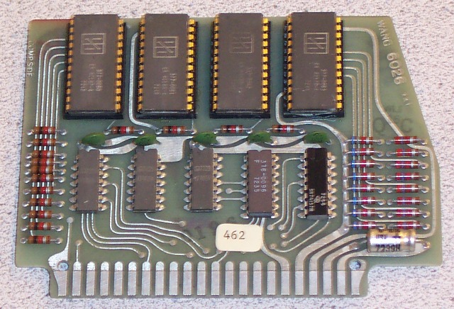
Additional ROM located on a half-wide plug-in board (Board #6026, the "Personality ROM) provides the hard-coded (likely coded in 400-series learn-mode keycode sequences) programs to implement the specific higher-level math functions provided by each model of calculator. For example, the 462 Statistical calculator exhibited here has four ROMs (Wang Part Numbers 377-0060 through 377-0063) containing the programming for the complex statistical math functions that are hard-wired into the calculator. Depending on the model of calculator, the 6026 board will be populated with different ROMs (the Model 450 uses only one ROM, Part #377-0047; the Model 452 uses two ROMs, Part #377-0048 and 377-0049; and it is currently unknown how many and what part number ROMs are used in the Model 487 Surveyor) to make up the specific functionality of each individual model. The ROMs used were also mask-programmed parts made for Wang Laboratories by Electronics Arrays, and are arranged as 512 words of 4 bits each, for a total of 2048 bits per chip. The personality ROM board contains five small- and medium-scale IC's for address decoding and buffering, along with pull-up and termination resistors, and an electrolytic bypass capacitor. It appears that sometime after the introduction of the 400-series calculators, a revision of the 6026 board was made to use eight Intel 1702 256x8 Eraseable Programmable Read Only Memory (EPROM) ICs rather than the Electronic Arrays-made 512x8 Mask-Programmed ROMs. The Intel 1702 was the first mass-marketed EPROM chip, introduced in 1972. This replacement board, designated 6030, was plug-compatible with the 6026. The use of EPROM allowed Wang to move away from expensive mask-programmed ROMs to less expensive overall, and easily programmable (and erasable by exposure of the chip to ultraviolet light through a window in the package) at Wang's facility. It seems that later model 400-series calculators were manufactured using this 6030 board rather than the 6026, as Wang's IC Reference shows Wang Part numbers 378-0010 through 378-0017 as containing the statistical functionality for the Wang 462, using the Intel EPROM devices. Both board 6026 and 6030 are accessed four bits at a time, and can address a maximum of 1024 eight-bit program steps.
The #6267 RAM Board in Base form (Note extra unpopulated area with space for eight optional 1101 RAM chips for the "-1" RAM option.
The main memory of the calculator, included on full-width plug-in daughter board, uses Intel 1101A 256x1 RAM (Random Access Memory) devices. It is within this memory that all of the working registers, memory registers, program storage steps, as well as various operating state information for the calculator is stored. There were two different memory boards that were available for the 400-Series machines. The earliest, board #6025 (not used in the calculator exhibited here), provides a total of 320 steps of program memory along with the other memory register to store memory registers, working registers, and status information. Later, it appears that a reworked version of the 6025 board was made, designated board #6267 to allow the board to be populated populated with eight or sixteen RAM chips, with a jumper on the board providing selection for whether the board is populated with eight or sixteen memory chips. Regardless of which board was used sixteen positions for RAM chips are present on the memory board. Based on the early 6025 board, it may be that the Wang 400-Series machines originally were introduced with maximum memory installed. Perhaps later, for competitive reasons, the base machine was changed to only provide 64 (with only half of the RAM chips installed) program steps, with the additional 256 steps added by populating the other eight RAM positions, and changing a jumper to a resistor. The Option 1 6267 board filled out the added 256 program stpes, providing the maximum amount of memory capacity for the board, for a total of 320 program steps (1024 binary-coded decimal digits, or 512 bytes). Both the 6025 and 6267 boards also contain power supply logic to generate the necessary voltages for the Intel 1101A RAM chips (which reguire some unusual voltages and current levels), as well some logic relating to selecting memory content (as a learn-mode program codes) or codes from the keyboard into the microcode sequencing circuitry.
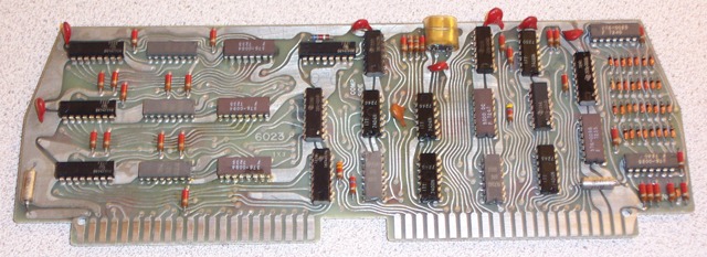
The 6023 Timing & Microcode Sequencing Board
Board #6023, a double-wide plug-in board, is also common to all of the Wang 400-Series calculators. This board provides the main timing and microcode decoding and sequencing for the machine. It includes a 4.0MHz crystal oscillator, along with various counters that divide the main clock frequency, and combinatorial logic that creates various state combinations. These state combinations are then used to fetch, decode, and generate the various timing signals that implement the microcode instruction set that serves as the "operating system" (for lack of a better term) for the 400-Series calculators. The microcode instructions are stored in the common ROM located on the motherboard.
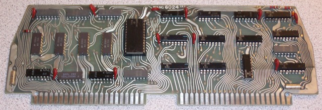
6024 Arithmetic Logic Unit Board
Also common to the 400-Series calculators is a full-width plug-in ALU (Arithmetic Logic Unit) daughter board (Board #6024) that utilizes only 25 small-and medium-scale integration devices, including a Texas Instruments 74181 4-bit full-adder, to provide the basic arithmetic and logical function for the machine. Basic math (add/subtract) in binary and binary-coded decimal modes, along with logical operations are carried out four bits (one Binary-Coded Decimal digit) at a time, in parallel. The ALU board for the 400-Series calculators is almost identical to that used in the Wang C-Series calculators, except the C-Series ALU is of slightly different logic design. The C-series ALU board will not work in a 400-series calculator, and vice-versa.
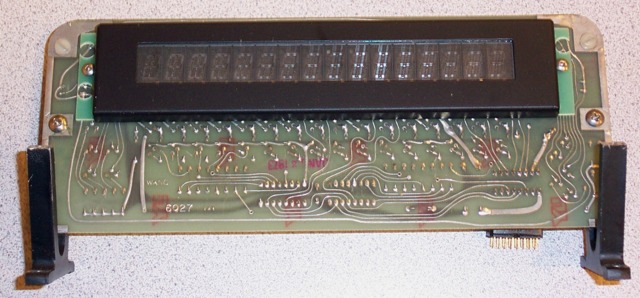
The 6027 Burroughs Panaplex Display Subsystem
For the display, the 400-Series and C-Series machines share the same display subsystem (Board #6027) utilizing an IC-based 7-segment decoder, with transistorized drivers for the multiplexed 16-digit position Burroughs Panaplex display. The actual display panel module is identical to that used as the display in the Wang 600-series calculators. The display sub-system connects to the main board using a sixteen-pin DIP header at the end of a length of spectra cable. The display system suppresses the display of insignificant leading zeroes, but does not suppress trailing zeroes in results, and automatically positions the decimal point when in floating point mode. In scientific notation mode, the decimal point is always located after the first significant digit in the number shown on the display.
The display rendition is seven-segment, with addition of two vertical bars in the middle of the "8" which allow the digit "1" to be centered within the digit. This rendition also allows easy generation of the "+" and "-" signs used for display the sign of number in the display, or the signs of the mantissa and exponent when the display shows a number in scientific notation. Additional logic combined with the IC-based BCD-to-Seven-Segment decoder chip provides the means by which the digit "1" is centered versus the standard position of the right-most two vertical segments being lit. Decimal points are positioned at the lower right of each digit. The decimal point is displayed alone in a digit position, which is a characteristic that the 400-Series calculators share with the Wang 600, and carries through to the C-Series machines.

Back side of 6027 Display Board showing display drive circuitry
The 400-Series machines provide display of thirteen significant digits (the maximum number in floating mode is "+999999999999.9 "), as well as providing scientific notation, with the mantissa containing ten significant digits, and the exponent ranging from -99 to +99. If the number to be displayed is too large to display with thirteen significant digits in floating display mode, the display automatically shifts into scientific format. An alternate action switch on the console of the machine allows the machine to operate in automatic (Fl) floating point mode in one position, or forces the calculator to always display in (Sc) scientific mode in the other position.
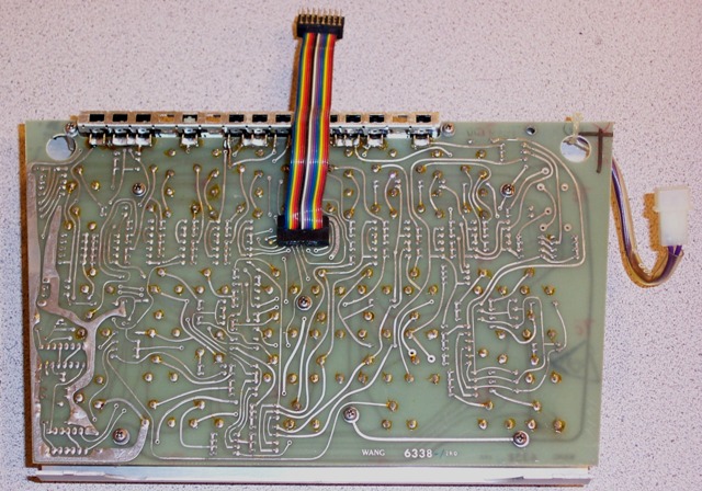
The back side of the #6338-2 Keyboard Assembly
It appears that the early production 400-Series calculators used Wang's tried-and-true microswitch keyboard design, where each keycap was connected to a stalk that had a disc that was pressed onto the stalk, that pressed down on the actuator button of a microswitch when the key was depressed. This original keyboard design dates back to Wang's first mass-marketed calculator, the LOCI-2. You can see detail of this type of keyboard construction in the exhibit on the Wang 360SE. This microswitch-based keyboard circuit board, designated boards #6028-2, was later replaced (likely to cut manufacturing costs), by a new design (board #6338-2)that used enclosed leaf-switch modules made by well-known switch manufacturer, Oak. These switches, while using high-quality gold-plated leaf contacts, were never quite as reliable as the original microswitch design that seemed virtually bullet-proof. The newer design keyboards are somewhat more susceptible to contamination getting inside the keyswitch modules, which can cause unreliable keyboard operation, including missed key depressions; or keyboard "bounce", where a single keypress results in multiple instances of the digit being entered. The later keyboards with the Oak keyswitch modules had a more conventional keyboard feel, with a longer throw on the switches compared to the short throw of the microswitch-based keyboards. Operators who were used to the microswitch-design keyboards of earlier Wang machines had a bit of a time adjusting to the keyboard feel of the new design keyboard. The 462 exhibited here utilizes the later design (#6338-2) keyboard assembly. The individual keys are encoded into a unique 8-bit code using a diode encoding matrix on the keyboard circuit board. Two Small-Scale IC's on the keyboard circuit board serve to condition the "key pressed" signal to insure that the "key pressed" signal is clean and consistent, independent of any contact bounce associated with the operation of the keys. It appears that the keyboard assembly in the Model 462 exhibited here was changed sometime during its life, as all of the rest of the components in the machine, and the final Quality Control inspection sticker date, are no later than February, 24, 1973. However, the keyboard assembly has a date stamp on it was made in October of 1973. It seems likely that the 462 exhibited here originally had the microswitch-based keyboard, and was replaced by the later Oak switch module-based keyboard assembly under warranty due to some kind of problem after the calculator was delivered to the customer.
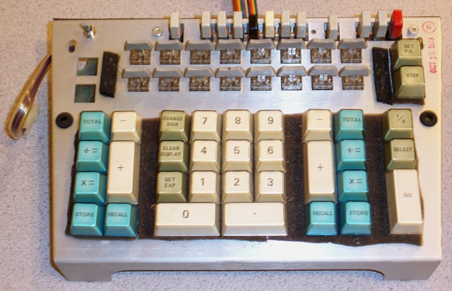
The Wang 462 keyboard Assembly
Though not confirmed as yet, it appears that the 400 and C-Series calculators gave up on Dr. Wang's ingenious idea of using logarithms for multiplication and division, instead using conventional shift and add (or subtract, for division) algorithms. While Wang's all prior machines (LOCI, 300/200-Series, 100-Series, 700-Series, and 500-Series) used logarithmic methods for multiplying and dividing (as well as providing more advanced math functions, such as square root), the computational accuracy of logarithms was never quite as good as the conventional add/subtract and shift algorithms, because most logarithms are transcendental numbers which can never be stated exactly even if extended to an infinite number of digits, thus creating a built-in inaccuracy (although limited by the use of non-displayed guard digits) in the logarithm-based calculators. It appears that the switch from logarithmic algorithms for multiply and divide to conventional shift-add/subtract algorithms may have occurred with the advent of the Wang 600-Series, and carried through the 400-Series, and lastly, the C-Series.

Wang 462 keyboard Layout
The control panel of the 400-Series calculators, while not looking too complex when compared to the daunting control panel of the Wang 700-Series machines, is actually rather complicated. Across to top of the operator's panel, starting from the left, is the power switch, a simple paddle switch. To the right of the power switch is a series of pushbuttons, most of which are gray in color, with two exceptions, one black, and one white button. The [CLEAR REGS] pushbutton is a momentary-action switch which clears all of the memory registers of the calculator when depressed.
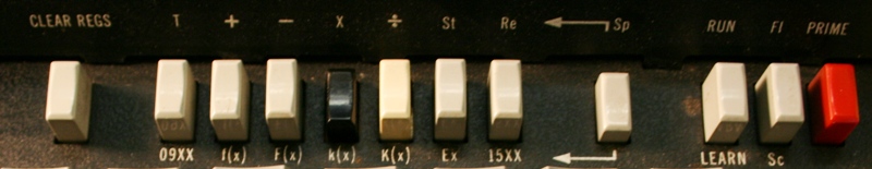
The "Special Operation" Selection Pushbuttons
Next to the [CLEAR REGS] button is a group of seven function control buttons that are mechanically interlocked so that only one of the seven switches can be depressed and locked down at any given time. This seven switches serve quite a number of roles, depending on the mode settings of the calculator (more on this below). We'll call these keys "Special Operation Selectors" To the right of these selector pushbuttons is another push-on/push-off button labeled [Sp]. This pushbutton determines the particular function of the "Special Operation Selector" pushbuttons. When the [Sp] switch is in the up position, the Special Operator Selector switches control the mode of operation of the sixteen memory registers that the calculator provides (more on how the memory registers are accessed is explained below). Each memory register in the 400-Series calculators can act as a complete four-function calculator, with the means to add, subtract, multiply, and divide, along with store, recall, exchange, and grand total. The Special Operation Selector buttons are labeled (as shown with legends above the buttons) as [T], [+], [-], [×], [÷], [St] and [Re], with the Exchange function located below one of the Special Operation Selection key, labeled [Ex]. The [T] selector acts line a "Grand Total" operator for the selected memory register. It recalls the content of the memory register to the display, then clears the memory register. The [+] selector adds the content of the display to the selected memory register, and stores the result in the memory register, leaving the display intact. Likewise, the [-], [×], and [÷] selectors subtract, multiply, and divide the number in the memory register by the number in the display, and place the result back in the memory register. The [St] and [Re] selectors simply Store the content of the display into a selected memory register, destroying its previous contents, and Recalls the selected memory to the display, leaving the content of the memory register intact, and destroying whatever number was originally in the display. The memory function operation selected by the selector switches is carried out when one of the 16 function keys (which among their other functions, serve as memory register selection keys) is pressed (see below). Lastly, the [Ex] selector (with the [Sp] switch in the down position) exchanges the content of the display with the content of the selected memory register.
When the [Sp] switch is in the down position, the seven
Special Operator Selector buttons take on new functions, relating to programming
and selection of built-in math functions. These functions are identified by
nomenclature printed below each of the Special Operator Selector keys.
Unfortunately, no documentation has yet been found for the 400-Series
calculators, and so some of
the functions in this grouping have not yet
been determined. Some have been partially decrypted through trial and error,
and others were obvious based on documentation found
for the C-Series calculators, but other keys remain elusive in terms
of their functions. Known learn mode program codes are documented
in the Tech Notes document entitled
Wang 400-Series Program
Operation Code Table. These selectors, labeled from left to right, are
[9XX], [f(x)], [F(x)], [k(x)] (black in color), [K(x)], [Ex], and [15XX].
The black [k(x)] selector selects the math functions listed on the black
sections of the function keys (explained below), and the white [K(x)] key
selects the math functions listed on the white portion of the function keys.
The [9XX] and [15XX] selectors are used for depositing special program codes
into program memory when the machine is in learn mode. They appear to perform
no identifiable operation when the machine is in RUN mode and are entered
manually from the keyboard. When in LEARN mode, these selectors deposit
a program step that contains 09XX, where XX is the keycode (ranging from
00 through 15) of the Function Key depressed. Likewise, the [15XX] selector
deposits a program code of 15XX. (Program codes on the 400-Series
calculators consist of four digits, represented as two groups of two
digits, ranging from 00 through 15. So, for example, the [1] key on the
keyboard is represented as "0001" when deposited as a program step.)
The purpose of the 09XX and 15XX programming functions have not been
determined at this point, but are likely used for program conditional test
and branch functions, I/O functions, and access to other programming
functionality. The [f(x)] and [F(x)] selectors remain a mystery that
the author has not yet solved by experimentation. As explained above, the
[Ex] selector is a memory-related function that exchanges the content
of the selected memory register with the number in the display.
To the right of the [Sp] button is the [RUN/LEARN] mode pushbutton. It is a
alternate action pushbutton (push-on/push-off) that selects whether the
calculator is in RUN (normal calculator) or LEARN (programming) mode. When
this switch is in the up position, the calculator operates normally as a
calculator, and can be made to execute programs stored in program memory
through the use of the [GO] and [STEP] keys. When the [RUN/LEARN] button
is in the down position, the calculator is switched into LEARN mode,
where program steps are entered from the keyboard, and stored
into the 400-Series program memory. More information on Learn Mode
programming of the 400-Series will be presented later in this exhibit.
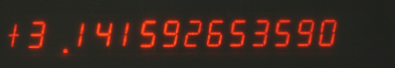
Display of number in floating point notation
Next in the bank of pushbuttons is the [Fl/Sc] button. It too is an
alternate action switch. In the up position, the display operates in automatic
floating decimal mode. If the number in the display is too large to be
displayed within the thirteen significant digits of accuracy, the display will
automatically switch to scientific notation to provide the most accurate
result.
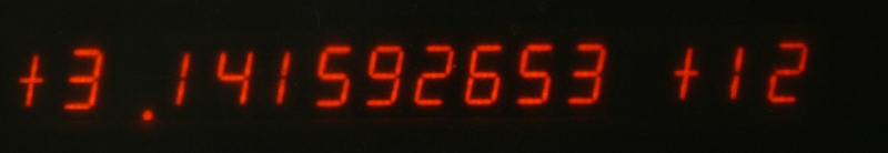
Display of number formatted in Scientific Notation
When this switch is in the depressed position, the calculator
will always display all results in normalized (with the decimal point
fixed after the most significant digit of the number being displayed)
scientific notation, of the form ±X.XXXXXXXXX ±YY, where the X's (mantissa) indicate the
most significant
ten digits of the number, and the Y's (exponent) represent the two-digit
power of ten to which the mantissa is to be multiplied for the actual answer, and ±
indicates the sign of the mantissa and exponent. For example, scientific
display mode, the number 2 would be represented in the display as
"+2.000000000 +00",
while the number 6-quadrillion, 350-trillion would be represented in the
display as "+6.350000000 +15".
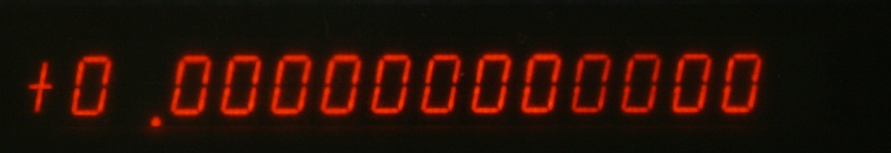
Display after pressing [PRIME] key in Floating Decimal Mode
Finally there is a red momentary action pushbutton labeled [PRIME].
Pressing it resets the error condition and clears
the display to "+0.00000000000 " (in floating decimal mode, or
"+0.000000000 +00" (in scientific display mode), setting the programming
sequencer's program counter to "0000", as well as clearing the
machine's general sequence control logic and state. The memory registers,
LEFT and RIGHT accumulators, and program memory is not disturbed by
activation of the [PRIME] button. Primarily, the [PRIME] key is used for
clearing an error condition, or for halting the execution of a runaway
program (e.g., a program with an infinite loop).
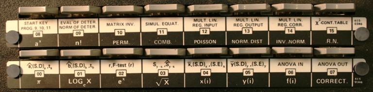
The Function Keys with their Labels
Located below the various function pushbuttons is a group of two rows of
eight "slim" gray keys, which we shall call the "Function Keys". These keys are
momentary action keys (made with the Oak keyswitch modules) that also provide
a selection of functions depending on the mode the calculator is operating
in. These sixteen keys can provide access to the sixteen memory registers
of the calculator, as well as access to 32 special math and programming
functions determined by the ROM personality module installed in the machine.
In the case of the Model 462, these functions relate to the advanced
statistical capabilities of the calculator.
Strips of plastic-laminated paper are fitted above each group of eight
function keys, retained by plastic pins, that serve to identify the functions
of each key. This meant that no specialized keyboard bezel nomenclature
for each model would have to be created. In the center of each key's
identification is a number ranging from 00 to 15. This number is used to
represent the memory register that the Function Key can represent when operating
on memory registers. The white area of the Function Key identifier
strips indicates the function executed (or
stored as a program step when in LEARN mode) when the [Sp] Special Option
pusbhutton is in the up position, and the white [K(x)] Special Function
Key is depressed. The black area of the Function Key identifier
strips identifies the function
executed (or, again, stored if the calculator is in LEARN mode) if the
black [k(x)] Special Option pushbutton is depressed. In LEARN mode,
the program step generated contains information relating to the setting of
the [Sp] switch, the Special Option key that is depressed, and the Function
key that is pressed.
When operating in RUN mode, manipulating the memory registers is pretty
straight-forward. The [Sp] key needs to be in the up position so that the
Special Option control switches can select the mode of memory operation
(except in the case of the Exchange operation [Ex], where the [Sp] key
needs to be in the down position).
All that is necessary is to select the operating mode for the memory operation
using appropriate Special Option control switch, then press the Function
Key associated with the memory register (as indicated on the key legend
strips), to select the memory register (00 through 15), and the selected
operation will be immediately carried out on the selected memory register.
For example, to add the current content of the display to memory register
12, [Sp] key must be in the up position, the Special Option key for [+] is
in the down position, then Function Key 12 would be pressed, and
immediately the content of the display would be added to memory register 12,
with the result stored in memory register 12, and the display remaining
as it was. To manipulate memory registers when in LEARN mode, the same
procedure is used, but a program step is created and stored in
program memory to indicate the operation to be performed when the program
is run. This program step contains information on the setting of the
[Sp] pushbutton, the memory function
selected by the Special Option switch setting, and the Function Key depressed
that indicates which memory register is to be operated upon.
To the right of the Function Keys are two standard keys that are used for
programming operations. The [SET P.C.] key is used in RUN and LEARN modes
to set the learn-mode programmer's program counter to the four digit number
entered after depressing the [SET P.C.] key. For example, to set the Program
Counter to 300, the [SET P.C.] key would be pressed, followed by [0], [3], [0],
and [0]. When the [SET P.C.] key is pressed, the display is blanked, with only
the left-most digit position showing a "+". Digit entries are displayed
left-justified on the display as they are entered, until four digits have
been entered. All non-numeric (e.g., not digits zero through nine)
are ignored. Once the four digits have
been entered, the display returns to the state it was in before the [SET P.C]
key was depressed. Contrary to what one might expect, the [SET P.C.] key
does not generate a "Go To" instruction when the calculator is in LEARN mode.
Instead, it just provides a means to change the location of the program
counter. Pressing the [SET P.C.] key in LEARN mode performs as it does
in RUN mode, but after the four address digits are entered, the display
shows the address, and the program instruction located at that address. How
program branches and conditionals are coded to allow iterative programs
to be written, remains mostly a mystery, but trial and error have
found two instructions "MARK" and "SEARCH" that happen to have similar
coding as the Wang 600. This allows unconditional branching, but no means
to do conditional test/branch, which currently remain unknown
The program counter has an allowable range of 0000 to 1855. Entering any
number greater than 1855 results in the machine entering the error state,
which must be cleared by pressing the red [PRIME] pushbutton that implicitly
resets the program counter to 0000. The base Model 462 (Option -0) has program
storage for 64 steps (0000 through 0063). Trying to store anything in
steps beyond step location 0063 results in no operation occurring. Recalling
step memory to the display for steps beyond 0063 results in "1515"
(11111111 as stored in binary). The Option 1 version of the machine, with
eight additional Intel 1101 RAM chips brings the total to 320 steps (0000-0319).
Why the calculator allows the Program Counter to be set from the apparent
theoretical maximum of step number 0319 through step 1855 is unclear, as
there is no memory internal to the calculator that can be addressed within this
range. Perhaps the limit of
1856 steps was pre-programmed into the operating microcode of the 400-Series
machine to allow external memory of some type to be connected to the I/O
interface of the calculator. Such a peripheral was developed for the
Wang 600-Series/700-Seres (the Model 618/718 External Memory Unit), so it seems
plausable that a similar peripheral may have been planned for. If such a
periperal was available, I've seen no documentation indicating its
existence. It seems an interesting coincidence that
1855 - 320 = 1536, an even boundary of a power of two, which could indicate
that an external memory device may have been planned for that added
another 1536 (1.5K bytes) steps of program memory. Until Wang documentation
(Advertising, Marketing/Sales Literature, or product manuals) on the 400-Series
can be found, this will also remain just an assumption.
Display shown using [STEP] key to step through 3 program steps
Below the [SET P.C.] key is a key labeled [STEP]. This key serves two
purposes. In RUN mode, it allows programs to be stepped through one program
step at a time, to help with test and debug of learn-mode entered programs.
In RUN mode, the calculator executes the current step pointed to by the
Program Counter, and shows whatever result the operation generated in the
display (as appropriate). In LEARN mode, the STEP key allows the user
to step through program step memory one step at a time, and observe the
content of the program memory. For example, if step 0 contained the
program code 0003 (the code for the [3] key), and step 1 contained 0007
(the code for the [7] key), and step 2 contained 0009 (the code for the
[9] key), with the calculator in LEARN mode, pressing [SET P.C.], [0], [0], [0],
[0] would result in a display of
" 0000 0003 ".
Pressing the [STEP] key
would advance the program counter to step 1, with the display now reading
" 0001 0007 ".
Pressing the [STEP] key one more time would result in
" 0002 0009 " in the display.
Below the Function Keys are the usual set of keys one might normally expect
on a calculator, including the basic math function keys (although
something that might be confusing is that the Wang 400-Series
provides two independent arithmetic function units, designated LEFT and
RIGHT which explains why there are two sets of keys relating to basic
math functions located to the left and right of the numeric entry keypad.)
In the center grouping of keys is the standard numeric keypad, with the
digits zero through nine, and decimal point arranged in the standard
calculator positions, with a double-wide zero and decimal point key below
the rest of the digits. It should be noted here that the decimal point is
displayed by itself in a single digit position, just as it is on the Wang
600-Series calculators. There are three additional keys in the numeric
entry block of keys, all
which aid in numerical entry. The [CHANGE SIGN] key changes the sign of
the number in the display, toggling between + and - each time it is pressed.
If the [SET EXP] key has previously been pressed, then the [CHANGE SIGN] key
toggles the sign of the exponent.
The display after pressing the [CLEAR DISPLAY] key
The [CLEAR DISPLAY] key clears the display
register, without affecting any other registers. This key is used to correct
erroneous input. When pressed, the display is cleared, displaying only
"+ ".
Digit entry procedes a digit at a time as entered, from
left to right. Lastly, the [SET EXP] key switches numeric entry from the
mantissa portion of a number into the exponent, for entering numbers
in scientific notation. The exponent may then be
entered by pressing numeric keys to complete the exponent entry. Once the
[SET EXP] key as been pressed, the machine stays in exponent entry mode until
the number is finalized by pressing one of the math or function keys.
For example, to enter the number 6.02×10²³, the keypress
sequence would be [6] [.] [0] [2] [SET EXP] [2] [3].
The exponent can range from -99 to +99. If extra digits are entered beyond
the two digit limit of the exponent, no error is presented, and the
new entry shifts the other digits to the left. For example, pressing [0] [.]
[6] [7] [5] [SET EXP] [1] [2] [3] [4] [5] will
result in "+0.675 +45" in the display.
Once this number is entered
into the calculator by pressing a math function key (e.g., the LEFT+ key),
the number is normalized and displayed as "+6.750000000 +44".
To the left and right of the numeric keypad are the control keys
for the "LEFT" and "RIGHT" arithmetic units, which operate identically
to their counterparts on the Wang 600, and have their genesis in the 300-series
calculators. Each arithmetic unit provides [STORE], [RECALL], [+], [-],
[×=], [÷=], and [TOTAL] functions. The [STORE] function
stores the number in the display into the arithmetic unit's accumulator
register. The [RECALL] key displays the content of the accumulator
on the display. The [+] key adds the number in the display to the
accumulator register, placing the result in the accumulator register, then
automatically recalls the accumulator register to the display.
The [-] key subtracts the number in the display from the accumulator register,
putting the result into the accumulator register, and then recalls the
result into the display. The [×=] key multiplies the number in
the display
by the number in the accumulator register, and places the result in the
accumulator register, and then displays the content of the accumulator register.
The [÷=] key divides the content of the accumulator register by
the number
in the display, placing the quotient in the accumulator register, then
automatically displaying the content of the accumulator register.
The [TOTAL] key recalls the content of the accumulator register to the
display, then clears the accumulator register to zero. With two complete
arithmetic units, the 400-series machines are very useful for business as
well as more complex math operations. It's interesting to note that the LEFT
arithmetic unit uses memory storage register 15 as its accumulator, and
the RIGHT arithmetic unit uses memory storage register 14 as its accumulator.
So, truly, there are really only 14 truly independent memory registers, with the
last two making up the accumulators for the LEFT and RIGHT arithmetic units.
This means that programmers have to be careful not to accidentally modify
the contents of memory register 14 or 15 during calculations. Such a mistake
could end up generating incorrect results that could be difficult
to debug.
At the right-most end of the keyboard are three keys, all of which serve
different functions. The [1/x] key provides the reciprocal function,
dividing 1 by the number currently in the display, and placing the result
in the display. The [SELECT] key remains a mystery, but is most likeely
related I/O interfacing. When the [SELECT] key is pressed in RUN mode,
the machine awaits one of the function keys (00 through 15) to be entered
before going back to normal operation, but when done so on this calculator
(which has no I/O devices plugged into it), no apparent operation occurs,
except in one odd case. Pressing [SELECT], followed by Function Key 07,
results in the machine's screen blanking for about a second, then coming
up with a blinking display (error indication). It seems that this
particular combination is similar to pressing the [GO] key to begin program
execution, but not quite, as setting the program counter to 0000, then
pressing [GO] results in a different number in the display than doing the
same process, but pressing [SELECT] followed by function key 07.
In LEARN mode, the SELECT key still waits for an additional function key
to be pressed, but no operation code is stored. The same combination
of [SELECT] and function key 07 result in the same situation as in RUN
mode, except at the end of whatever is happening, the display comes up
blinking, with step number 1855 showing, with a content of 1515.
in program memory. Lastly, the double-tall [GO] key is used in RUN
mode to cause the calculator to begin or continue execution of a program
stored in memory at the current location pointed to by the program counter
(see the description of the [SET P.C.] key above). While stored programs
are running, the display is mostly blanked, with the left-most digit or two
positions flickering dimly. If the [STEP] key is pressed while a program
is running, the calculator will immediately stop execution of the program
after the current step finishes processing, and the calculator enters
single-step mode, where each press of the [STEP] key steps through the
program one instruction at a time. When in this single-stepping mode,
pressing the [GO] key will resume the program running at full speed.
While single-stepping through a program in RUN mode, the display shows
whatever it would during manual operation of each keypress in the stored
program.
On the Model 462, the function keys provide
access to a comprehensive selection of complex statistical functions.
including factorial; ax; ex;
square root; basee logarithm; data entry for lists or
arrays of numbers; calculations of permutations and combinations; mean,
median, standard deviation, and standard error; matrix inversion;
solution of simultaneous equations; and generation of random numbers
(between -1 and +1) [R.N.]), along with a whole host of other statistical
functions that the author admits to not having much of an understanding of,
such as [ANOVA IN/OUT] (Analysis of Variance), [POISSON] (Poisson Distribution)
[NORM. DIST] (Normal Distribution), and others (See image above).
The function shown on the white part of the key label is executed if the
white special function pushbutton (more on the special function pushbuttons
later) (labeled [K(x)]) is depressed, and the likewise, the function in the
black part of the key label is executed when the black special function
pushbutton (labeled [k(x)]) is depressed.
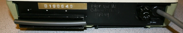
The rear panel of the Wang 462
The 400-series calculators have a connector on the rear panel for addition
of a peripheral devices. It appears that a mark-sense card reader
called the Model 10 was available available for coding programs onto
mark-sense cards, making it easy to load pre-coded programs into program
memory. As explained above with regard to
program memory storage, it also appears that perhaps there may have been some
kind of external memory module that could be plugged into the external device
connector that allowed additional program memory to be accommodated. The
I/O connector does appear to support bi-directional communication, as well
as a means to select up to sixteen external devices. It is not known if
external printers, plotters, paper tape, magnetic tape, and other I/O devices
available on the earlier 700, 500 and 600-Series calculators were made
available for the 400-Series. Along with the I/O connector on the back panel,
there is a fuse holder for the mains fuse, and an entry point for the
fixed power cord. In the photo above of the back of the machine, you will
note a plastic strip covering the I/O connector. These strips helped
protect the connector from physical and electrostatic damage when the I/O
connector was not being used.
The machine is mostly complete in catching
error conditions. Numeric under/overflow is always detected, and indicated by
flashing the display at a 2Hz (two blinks per second) rate. This error
indication does not lock out the keyboard. Operations may continue as normal
while the machine is in error state, but the display will continue flashing to
indicate that the resultant answer is not to be considered accurate.
Illegal input to most math functions, such as dividing by zero, extracting
the square root of a negative number, performing a logarithm of zero, etc.,
will all trigger the flashing display indication. However, it appears that
the Model 462's factorial algorithm wasn't coded with error detection in mind.
Performing the factorial of a negative or non-integer number results in the
machine going into an infinite loop, with the left-most digit of the display
flickering with a rhythmic pattern. The only way to stop this behavior is to
press the [PRIME] key. When the error condition is indicated
by the flashing display, the only way the condition be cleared
(without turning off the calculator) is by pressing the red [PRIME] key.
It should be noted here that the power-on clear logic/microcode of the
machine doesn't seem to be that reliable. A good percentage of the time
when first powered up, the machine comes up with all of the registers cleared,
and the display showing
"+ ". However, sometimes the machine leaves garbage numbers
in the display and memory registers (and thus, the LEFT and RIGHT
accumulators), and can create some confusion. The author would guess that the user's
manual (if one can be found) says to assure that the machine is ready for
operation after power on, to press [PRIME], followed by [CLEAR REGS].
This would force all of the registers and calculator status to be set
to begin normal operation.
The Wang Model 462 is a a reasonably fast calculator. In some cases, it seems
faster than the Wang 700-Series, which is one of the fastest high-end
programmable calculators that the museum has come across. However, in
other cases, it is definitely slower. The reason for this seems to be
that some of the advanced math functions, such as square root, are implemented
as "learn mode" program codes stored in the Personality ROM, which are
slower to execute than microcoded routines to perform the same function used
in the 700-series machines.
With a base clock frequency of 4MHz, and all bipolar small- and medium-scale
logic, with fast Metal-Oxide Semiconductor (MOS) RAM and ROM, the
462 is significantly faster than many later-design calculators that
used MOS/LSI chipsets for their logic. As yet, no performance
specifications for the 400-Series calculators have been found, so
approximation for the actual time it takes for an operation to complete
is all that can be used to compare the speed of the machines.
The basic math functions on the 462 complete virtually
instantaneously. Computing 69! (with the ! representing a function
called factorial, e.g., 69! would consist of carrying out the following
calculation:
1 × 2 × 3 × 4 × ... × 69). 69! is
the largest factorial the machine is capable of representing without
overflowing (the result shown on the display of the calculator at the top of
the exhibit is +1.711224524 +98), takes approximately 600 milliseconds
(0.6 seconds) to complete, which is quite fast. Some of the more advanced
statistical functions can take a significant amount
of time to process, in some cases, up to about five seconds, however, not
having a strong background in statistics, it's not at all sure
that the computations being made make mathematical sense.
As far as executing learn-mode stored program
steps, the entire 64 steps of program memory was filled with what appears
to be "No Operation" instructions (code 1515). Then this "useless" program
was started at step 0000. This essentially caused
64 no operations to occur. Once the 64 keyed-in No Operation codes were
executed, the remaining non-existent memory from step 65 through 1855
also return the No Operation instruction, meaning that the machine just
kept executing no operation instructions until it hit the limit of the
Program Counter of 1855, at which time it went into error state due to the
Program Counter trying to step to the next location (1856), which is beyond
the allowable maximum. The whole process of executing this so-called program
took about 3/4 second, indicating that (while the No Operation code
is the most lightweight operation the calculator can perform) the machine
can execute learn-mode programs at as fast as 2000 steps per second....
Of course, the timing of a program performing an actual
mathematical algorithm would depend on the complexity of the math
operations being performed,
the number of loops and conditionals and other variables that could
cause programs to run for very significant periods of time. In time, it
is hoped that the function of various unknown operation codes can be
determined either by finding documentation for the 400-Series, or by trial
and error.
Once information can be found on the various programming instructions
for the 400-Series machines, then some real programs can be
written for the machine to see how it actually performs doing real-world
calculations. On the positive side, in studying the program codes for the
600-Series calculators, it appears that the 400-Series machines share many
of the program codes, so perhaps trying some of the programming-related
function codes from the 600-Series may result in some progress toward
figuring out how this machine is programmed, but that remains a project
for another time. Of course, if you know of any Wang 400-Series documentation
(operator's manual, programming manual, service documentation, or
advertising) please let me know about it by
Sending an EMail.
During calculation, the 462's
display is generally blanked, though the left-most two positions in the display
flicker segments randomly as built-in and pre-programmed math functions are executed. Other
times, only the right-most digit position flickers. It is not clear why
this occurs, but is perhaps an artifact of the way the circuitry is designed,
or something to do with the way that the microcode is written.
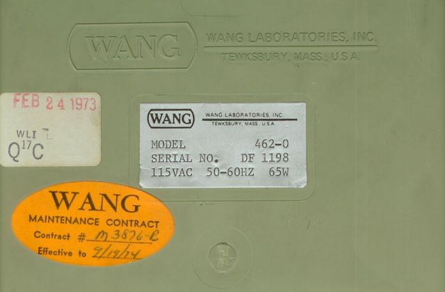
Various tags located on the bottom of the calculator
The particular Model 462-0 calculator
exhibited here appears to have been completed and given its final
Quality Assurance inspection on February 24th of 1973. Date codes on
most of the components in the machine (except the keyboard assembly, which
appears to be a replacement with a date stamp in October of 1978) are earlier
(early-1972 through early-1973) than final QA date. The main motherboard
assembly has a QA date of February 14th. On the bottom of the
machine, there are three tags; the final QA sticker, the model/serial number
data tag, and the familiar Wang
dayglow orange oval sticker which marked the machine as being covered by a
Wang maintenance contract beginning in September of 1974 (after the
manufacturer's one year parts warranty had expired). This
could indicate that the machine was originally purchased sometime in
September of 1973, and after a year elapsed, the owner opted to provide
continued maintenance support under contract with Wang. This would mean
that the calculator remained in stock at Wang or an authorized distributor for
a period of approximately 6 months before it was sold.
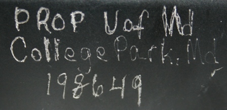
University of Maryland identification engraved on back panel of calculator
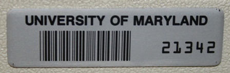
Barcoded University of Maryland Asset Tag
The machine was purchased new by the University of Maryland, as there
is "Prop. of U of Md, College Park, Md, 198649" etched into the black
paint of the rear panel of the machine. Later, a tamper-resistant barcoded
metal asset tag was affixed to the left side of the calculator also stating
ownership by the University of Maryland, with a different item number, perhaps
indicating that the university's asset tracking system was updated
during the time the calculator was considered an asset to utilize
barcode technology, that, by the mid-1980's, had become inexpensive
enough for organizations with large inventories of items to deploy as an aid
to identify and track assets. Given the nature of the calculator, it was
likely used in the mathematics or scientific curriculum at the university.