
| +Calculators | Wanted | Advertising | Articles | Links |
| +Calculators | Wanted | Advertising | Articles | Links |
The Victor 3900 - History's Forgotten Miracle
By Rick Bensene
January, 2011
Updated 4/19/2024

The Victor 3900 was a true breakthrough in electronic calculator technology (arguably electronics technology in general), though its historical significance has been somewhat shrouded by the mists of time. A sad truth about time is that information becomes stale, memories fade, and, especially with technology, newer technologies redirect attention, somewhat diminishing the significance of earlier technological triumphs. This essay is an attempt to illuminate the story of the Victor 3900.
Sincere thanks are due to Bob Norman and Don Farina, both co-founders of General Micro-electronics who both shared a great deal of information about the development of the Victor 3900 with the author through telephone conversations, EMail, and an in-person visit by Bob Norman. Both of these men hold major places in semiconductor history, and along the way have made many contacts with others who were involved in the semiconductor industry of the time. Both men worked very hard to unearth and document many of the details that prior to their efforts had been lost to time. The author also additionally wishes to thank Bob Norman for taking the time to come visit the museum in May of 2009. Bob spent 3 1/2 hours at the museum, and shared many wonderful memories of the amazing times at General Micro-electronics, as well as stories about Nortec Electronics, the company he founded after leaving General Micro-electronics.
Thanks are also due to Mr. John Kendall, a Victor technical service representative for 28 years (August, 1959 through September, 1977), who owns an operational Philco-branded 3900 calculator. John shared a great deal of information relating to his machine, including many photos that are included in this essay, which is deeply appreciated. The Old Calculator Museum owes all of these gentlemen a debt of gratitude for taking the time to document their memories, as well as put up with a seemingly never-ending stream of questions from the author.
When the introduction of the Victor 3900 occurred in late October of 1965, electronic calculators that existed used discrete transistor logic circuitry with various types of memory technology for storage of the calculator's working registers including magnetic core (Mathatronics Mathatron, Wanderer Conti); magnetostrictive delay lines (Friden 130, Diehl Combitron, Wyle Laboratories WS-02, Monroe EPIC-2000/3000); transistor-based shift registers (Sharp Compet 20 CS-20A, Wang LOCI-2, Canon 161); Cold-Cathode Tube-based ring counters(ANITA Mk7, ANITA Mk8, ANITA Mk9, ANITA Mk10); and a unique refreshed charge capacitive memory (Toshiba TOSCAL BC-1411). All of these technologies had their place in making electronic calculators a practical commercial product, but were bound to obsolescence with the advent of Large Scale Integration(LSI) MOS integrated circuits.
The Victor 3900 broke completely new ground with the entirety of its logic and storage implemented with integrated circuits, and took things yet a major step farther by using MOS(Metal-Oxide Semiconductor) LSI integrated circuits. At the time, MOS integrated circuit technology was in its infancy, and the development of MOS LSI technology to make the Victor 3900 possible was an unprecedented accomplishment that made the machine an absolute revolution in the design of digital logic, not just for calculators, but for anything that required digital electronics. Most notably, the advent of large-scale MOS integrated circuits had folks in the military weapons, countermeasure, communications, and reconnaissance fields very intrigued, as well as the "no such agency" aspects of the US National Security infrastructure.
At the time, earlier bipolar digital integrated circuits were mainly used by the US National Security Agency(NSA), the US military forces, and the US space program. Some bipolar integrated circuits were also beginning to show up large mainframe computers. Digital ICs were still quite expensive and were considered specialized technology, used in environments were cost was less of a concern than the power, size, reliability and weight savings associated with the use of integrated circuits. The integrated circuits being used in these applications were mainly bipolar devices that shrunk down conventional transistors and other components to yield a small number of logic gates or a few flip flops on a single chip -- amounting to a practical maximum of around one hundred equivalent transistors per chip. The level of integration provided by the integrated circuits used in these applications was later called Small Scale Integration (SSI). In time, bipolar IC technology developed to allow more devices on a single chip, creating a new classification of devices called Medium Scale Integration, or MSI. Despite the advances, it was clear that there were limitations to bipolar IC technology. As the complexity of bipolar devices grew, there were scaling problems that were not easy to solve, including issues with heat dissipation, power distribution, and process issues that limited just how much logic could practically be put on a single chip.
While bipolar integrated circuits were a huge advancement over discrete transistor electronics, their limitations became a problem when it came to development of highly complex digital systems such as those used in precision weapons systems and decryption of electronic communications of interest to the US government. The fabrication of bipolar transistors in integrated circuits was complex. There were also limits on how small bipolar transistor could be made. Bipolar transistors fabricated in integrated circuits were rather power-hungry, though they did use much less power than discrete transistors. Keeping the chips cool in complex systems where hundreds of ICs were used also became an issue, especially in situations were there were limited size and weight resources for cooling, such as in the electronic guidance system of a ballistic missile. These limitations left IC technologists thinking that there had to be a better transistor technology than bipolar transistors to use to make the ever more complex ICs that these entities required.
That better technology turned out to be Metal Oxide Semiconductor technology, or MOS for short. Transistors implemented using MOS technology turned out to be much less complex to fabricate, consumed considerably less space, and used less power than their bipolar counterparts when fabricated into IC's. The development of MOS IC technology created the beginning of what later came to be called Large Scale Integration devices, where vastly more transistors could be put on a single chip. The acronym LSI is still in use today to describe the amazingly complex chips that can be made today. Today's LSI chips can contain hundreds of millions of transistors. The LSI chips that made up the Victor 3900 had many orders of magnitude fewer transistors (around 250 per chip), but at the time were a truly breathtaking accomplishment.
In the early 1960's, MOS integrated circuits were the stuff of research laboratories in universities and large semiconductor manufacturers such as RCA, Fairchild, Motorola, and Texas Instruments. Few people were convinced at the time that MOS devices were to be the IC technology of the future. Some of the early experiments to develop higher-density ICs made with MOS transistors met with failures that were partly due to a lack of a complete understanding of all of the physics involved. Issues with impurities that crept into the fabrication processes, difficulties with aligning the photographic masks that are used to create the various layers of the IC that form the transistors and the interconnections between them, and also that making MOS integrated circuits required completely new types of fabrication equipment that in many cases, had to be developed from scratch by the engineers since no such equipment had existed in the past, and there were trial and error issues with getting the equipment dialed in to produce ICs the consistently functioned properly.
Despite some of the doubts, a small group of visionaries at Fairchild Semiconductors saw the promise of MOS circuitry as a leap forward in technology. These folks tried to spur initiatives within Fairchild to develop MOS integrated circuits into production products. Fairchild was making tons of money with its bipolar IC's, and did not seem interested in diverting attention from IC technology that they had perfected the processes to create, and were continually improving those processes to make the ICs even less expensive to produce, all of which translated to more profits on the bottom line. The group of folks trying to push Fairchild to move into MOS ICs were not able get traction at higher levels of management needed to fund their initiatives, and as a result, a number of them left Fairchild in the spring of 1963 to start their own company. The long term goal this company was to make MOS integrated circuits a practical reality that could put more much complex logic onto a single chip than had heretofore been possible. More on that later in this story.

Texas Instruments' Cal-Tech Prototype
It took until spring, 1969 before an electronic calculator that successfully utilized large-scale MOS integrated circuit technology would be available for commercial sale. That calculator was made in Japan by Hayakawa Electric Co., Ltd. (which changed it's name to Sharp Corporation in early 1970). The machine was the Compet QT-8D, introduced in March of 1969. The QT-8D utilized a four-chip LSI chip set developed and fabricated by the Autonetics division of North American Rockwell exclusively for Hayakawa Electric. Autonetics was among the few companies that were able to produce large scale MOS integrated circuits in the late part of the 1960's. Along with Autonetics, there was American Micro-systems, Inc.(AMI), and General Instrument. It is important to remember that the Sharp QT-8D was introduced a full four years after the introduction of the Victor 3900. At the time the Victor 3900 was introduced, MOS IC's were only beginning to be investigated by the Research & Development department of Autonetics, and AMI had just recently opened up for business in July of 1966, after a group of engineers from General Instrument that were frustrated with the rate of progress of MOS development there decided to start their own company to focus on MOS ICs.
The only other calculator to even come close to providing an advanced level of integration was Texas Instruments' very-limited prototype Cal-Tech handheld(it was a bit of a handful) battery-powered printing electronic calculator, which was implemented using four rather large bipolar integrated circuits that stretched the state of the art of bipolar IC technology to its limits. The Cal-Tech was somewhat limited in its capabilities, and though it did perform all four basic math functions, it only did so only with integer numbers, and had a capacity of only five digits. As is currently known, three Cal-Tech calculators were produced in 1967 that were shown as demonstrators of what Texas Instruments called it's "discretionary wiring" bipolar logic arrays.
These bleeding-edge chips were essentially large arrays of standard logic elements that were not connected to anything but power in base form. A layer of metalization was added on top of these logic elements that provided the connectivity between them to provide the desired logic functions to create the final IC. The discretionary aspect of the technology was that that metal layer that provided the connections between the standard elements could be computer-generated from a description of the logic equations for desired functionality of the chip. The concept was sound, and was later proven using MOS rather than bipolar transistors to make devices called Gate Array Logic (also called GALs), which evolved into what are now called Complex Programmable Logic Devices (CPLDs), where huge arrays of logic elements can be connected together by a programming process that electrically forms the connections between the elements, allowing the devices to be programmed to carry out very complex logic systems.
The challenge with TI's discretionary wiring logic arrays was that they were implemented with bipolar transistors, with all of the limitations that bipolar transistors had when scaled down to microscopic levels. In some cases, in order to get the ICs used in the Cal-Tech calculator to work properly, the devices had to be "patched" by removing connections to defective transistors and re-wiring them to good spare transistors all by hand, under high magnification through a microscope, while using micro-manipulators to do the "cut and re-wire" operations. The arrays were purposefully designed with a sprinkling of spare transistors on the chip just for this purpose, since it was known that there were bound to be defects in some of the transistors on the chip simply due to the difficulty fabricating bipolar transistors of this size. While this was fine for a proof-of-concept prototype technology showpiece, it was completely impractical for any kind of mass-produced device. The Cal Tech calculator was a truly amazing accomplishment, but only a few were made, ending up in the hands of members of the design team and later in museums.
The proof that the Cal-Tech design was something that could, with the proper technology, be turned into a production product came in April, 1970, when Canon's Pocketronic was introduced. The Pocketronic was essentially an improved-capability production version of the Cal-Tech, but was made with MOS LSI integrated circuits produced by Texas Instruments in collaboration with Canon.
While both the Cal-Tech and QT-8D utilized far fewer chips than the Victor 3900, the fact that it took so long for others to develop similar MOS technology is a strong indication of just how advanced the Victor 3900 was for its time.
The Victor 3900 is a fully self-contained, fully-featured (for the time) desktop electronic calculator. It uses a Cathode Ray Tube (CRT) that displays the content of five working registers of the calculator. The machine has a capacity of 20 digits, and provides leading zero suppression (as patented by GM-e in US Patent #3388384), a feature that, at the time did not exist on any display-type electronic calculator. The Victor 3900 has two independent accumulating memory registers that are displayed at all times, and a third store/recall memory register that is not displayed. The calculator carries out addition, subtraction, multiplication, and division automatically. It operates with automatic floating decimal point with a switch-selectable round-off position. It provides a ten-key numeric keyboard, using a combination of mechanical interlocks and electronic means to help the operator avoid input errors. The machine detects overflow and error conditions and sounds a buzzer when such conditions exist (a feature that likely caused some annoyance in office settings). Math problems are input using a combination of arithmetic (for addition/subtraction) and algebraic logic (for multiplication and division). The top line of the display shows the content of memory accumulator I, and the second line displays memory accumulator II. The next three lines display the arithmetic working registers of the calculator, with the top line in the group showing the first number of an arithmetic operation, the next line showing the second entry in a math operation, and the bottom line serving a dual purpose, serving both as the entry register, and also displaying the results of a calculation.
The story of the Victor 3900 begins in the early 1960's. The management of Victor Comptometer Corp., a very successful Chicago, Illinois-based mechanical adding machine and calculator producer, came to the conclusion that the days of mechanical calculating machines may well be numbered. At the time this conclusion was drawn, there were only rumors of future electronic calculators floating around, with no actual machines on the market. The English companies Sumlock Comptometer and Bell Punch were reported to be collaborating in the development of an all-electronic calculator based on miniature cold-cathode tube devices called Thyratrons (this development resulted in the Anita Mk7 and Mk 8 calculators). Word was also circulating that other mechanical calculator companies were working on developing electronic calculators, including Friden Calculating Machine Co., Monroe, and Smith Corona Marchant, along with some Japanese companies including Sony, Casio, and Hayakawa Electric (Sharp). With the price of transistors dropping rapidly, and a huge potential market, the idea of selling a desktop electronic calculator became very alluring, and organizations ranging from large corporations to individual inventors working in their garage workshops were enticed by the profit potential of a silent and fast desktop electronic calculating machine. Clearly, there were fortunes to be made, and the management of Victor Comptometer wanted to make sure that they were going to get in on these fortunes.
Victor's management embarked on a campaign to bring new talent into the company, people with a background in electronics. Through some acquisitions, along with an ambitious program of bringing in bright college graduate new-hires, Victor had gathered a enough of a critical mass of skill sets to enable it to begin the design of an electronic calculator. In 1962, a team of employees from all disciplines were tasked with building a prototype electronic calculator using vacuum tube technology. The goal wasn't to build a production desktop calculator, as doing so with traditional vacuum tubes simply wasn't practical. The project was more to develop and test the logic design and architectural concepts needed to make an electronic calculator. By the fall of 1963, a working experimental prototype calculator was running. The machine worked well, but literally filled a small room, required a lot of power, and made a lot of heat. The prototype clearly demonstrated that Victor had the digital design expertise to come up with a workable design for an electronic calculator that just needed to be shrunk down to a desktop form-factor to be a market reality. Although Victor had amassed a good level of talent, by the time the prototype was running, technology had moved beyond vacuum tubes. Almost all the newer computers were using transistors, and transistors were quickly replacing vacuum tubes in consumer electronics such as radios and televisions. Victor's management was concerned that it would take too long for the design to be re-implemented using transistors to reduce the size of the calculator to something that would be marketable. The fear was that by the time that work was done, the market would be brimming with competition that would negate a lot of the market power that Victor could gain by being one of the first to market. Along with the concern for time, Victor's management wanted their electronic calculator to be a technological tour-de-force, using bleeding-edge electronic technology to make a machine that would be unmatched-matched in the marketplace for a long time to come. The expertise to make this happen did not exist within Victor, and would be prohibitively expensive and time consuming to develop in-house. It was clear that Victor needed help from the outside to bring their vision to reality.
![]()
The General Micro-electronics Logo
Back to the story of the folks from Fairchild that spun-off to form their own company dedicated to the commercial development of MOS IC technology. Fairchild had become famous in the semiconductor world for its co-invention of the integrated circuit. The company had very successfully developed and marketed a family of bipolar Resistor-Transistor (RTL) digital logic chips (with the trade name of "µLogic", aka MicroLogic) that were making the company a lot of money. The µLogic chips have a major place in history, as the computers that ran NASA's Apollo spacecraft that eventually put a man on the moon were made from specially-prepared (processed and packaged for the unique rigors of space flight) Fairchild µLogic chips.
Because of an inability to get Fairchild interested in aggressive development of MOS integrated circuit technology, three Fairchild employees tendered their resignations in the spring of 1963 and went off to start their own company. Their goal was build a company that combined both systems and semiconductors; that focused on reliability and maintainability; and to provide the market with a one-stop solution to complex electronic systems and circuit design. These gentlemen were Bob Norman, Howard Bobb(later one of the founders of AMI), and Phil Ferguson. The biggest issue they faced was capital to really get the company going.

Col. Arthur Lowell, ca. 1969
This problem was solved when fourth gentleman entered the picture -- Colonel Arthur Lowell, the Commander of the Navy Bureau of Weapons. Lowell had connections with a company called Pyle National through his military work, and when Pyle National was looking to make some strategic investments, Lowell suggested that the business plan that Norman, Bobb and Ferguson had put forth held great potential for success. Pyle National was a very well established company specializing in the manufacture and sale of mil-spec electrical connectors, plugs, and sockets -- critical components in military equipment. Lowell's recommendation hit a chord with Pyle National's board of directors, and an agreement was forged by which Pyle National put up between $4 and $5 million dollars of capital to get the the Fairchild renegades started. The new company was named General Micro-electronics. The founders got right to work, and by August of 1963, they had found a building at 2920 San Ysidro Way in Santa Clara, California (literally next-door to Fairchild), hired staff (many from Fairchild, an act that eventually landed GM-e in court due to a lawsuit filed by Fairchild), and acquired and/or built the equipment necessary to start making IC's right away. Their first charge was to develop their own line of (Fairchild µLogic-compatible) bipolar ICs to use as a way to raise money to help fund the development of their MOS integrated circuit processes. This family of bipolar logic ICs were quickly developed and marketed by GM-e under the trade name of "Milliwatt Logic". These chips were compatible with Fairchild's µLogic family, offering similar or identical functionality to Fairchild's chips. Since the chip designs were GM-e's own designs, not taken or patterned after Fairchild's chips, there was little that Fairchild could do about it, though Fairchild made rumblings about taking GM-e to court, in this case, they did not follow-through.
Prior to leaving Fairchild, Bob Norman had been involved in lucrative government projects involving the use of Fairchild's µLogic for use in various military and defense applications. With Norman's connections and Arthur Lowell's contacts within the military, GM-e was able to get the government interested in their Milliwatt Logic family for a number of projects. One project, a Digital Differential Analyzer used for helicopter flight controls, needed a level of integration that was more complex than Milliwatt Logic could provide within the size and power constraints of the design. This project provided the impetus for GM-e to get its MOS fabrication line up and running. In June of 1964, GM-e had successfully developed a MOS dual 20-bit dynamic shift register (US Patent #3,454,785) that would be used in the military's Digital Differential Analyzer. This IC, designed by Bob Norman, was the first commercial MOS IC produced, and set the stage for a literal revolution in the world of integrated circuits. On the success of this design, the US Department of Defense put in an order for a more complex two chip set for use as a fuse timer for munitions. Twenty-five chip sets were shipped on New Year's Day, 1965, and every set worked perfectly. GM-e's MOS manufacturing process was now tried and true. On these successes, GM-e developed a line of small and medium-scale MOS IC's marketed as the "PicoLogic" family. However, all of these MOS devices, while packing more transistors in a single chip than had been done before, were not nearly to the scale of complexity that GM-e would eventually need to develop for Victor's calculator.
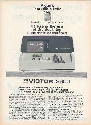
An Early Advertisement for Victor 3900
With the introduction of the Victor 3900 in late October of 1965, all electronic calculators that were on the market at that time utilized discrete transistor logic circuitry and various types of memory technology for storage of the calculator's working registers. Some examples of memory technologies used and some calculators that utilized them are: Magnetic core arrays (Mathatronics Mathatron Wanderer Conti), Magnetostrictive delay lines (Friden 130, Diehl Combitron, Wyle Laboratories WS-02, Monroe EPIC-2000/3000), Discrete transistor-based shift registers (Sharp Compet 20 CS-20A, Wang LOCI-2, Canon 161), Cold-Cathode tube-based ring counters(ANITA Mk7, ANITA Mk8, ANITA Mk9, ANITA Mk10), and a unique refreshed charge capacitive memory (Toshiba TOSCAL BC-1411). All of these calculators had their place in making electronic calculators a practical commercial product, but appeared to be doomed to instant obsolescence with the advent of Victor's Large Scale MOS integrated circuit-based calculator.
The Victor 3900 broke completely new ground, with the entirety of its logic and working register storage implemented with integrated circuits, and took things yet a major step further by its use of MOS LSI integrated circuits with levels of integration that were far beyond anything thus conceived. At the time, MOS integrated circuit technology was in its infancy, and the development of MOS LSI technology to make the Victor 3900 possible was an unprecedented accomplishment that made the machine an absolute revolution in digital electronic computing technology.
At the time, digital integrated circuits were mainly used by the US National Security Agency, the US military, and the US space program. IC's were just beginning to be used by large mainframe computer manufacturers such as IBM, Burroughs, and Univac. Digital ICs were still quite expensive and were considered specialized technology, used in environments were cost was less of a concern than the power, size, and weight savings that ICs provided. The vast majority of the integrated circuits being used in these applications were mainly bipolar devices which shrunk down conventional transistors and other components to microscopic size to yield a small number of logic gates or a few flip flops on a single chip. These chips amounted to a practical maximum of around one hundred equivalent bipolar transistors per chip, with most chips containing significantly fewer transistors. The benefits of using integrated circuits was that reliability increased, power consumption was considerably reduced, and heat dissipation was substantially less. However, most importantly, the amount of physical size and weight required to implement a given function was dramatically reduced. All of these factors were absolutely critical in military and space electronics.
Victor Comptometer had a developed a detailed list of requirements for the calculator they intended to bring to market. It was to be used for financial and scientific calculations that require more digits of capacity than was typical of most electronic calculators of the time. It had to have fully automatic floating decimal, with user-selectable round-off location. It needed two full capacity accumulating memory registers. It had to clearly display its two memory and three working registers at all times. It had to perform all four basic math operations fully automatically, and no calculation was to take more than 400 milliseconds (0.4 seconds, or 4/10ths of one second) to complete. All of this needed to fit within a self-contained desktop package with rough dimensions specified by Victor. Victor also wanted the calculator to utilize the very latest technology possible to make the calculator a showcase of Victor's technological superiority over all other competitors in the extremely competitive desktop electronic calculator market.
In October of 1964, GM-e and Victor Comptometer entered into a formal contractual agreement for GM-e to design and manufacture the specified calculator for Victor. Victor would pay GM-e $50,000 per month to fund the development of the calculator. GM-e was obligated to deliver the first 25 production units to Victor by April, 1965. If this deadline was met, GM-e would receive a bonus of $500,000. Though the calculators would be completely made by GM-e, they were Victor products, and Victor would provide all of the marketing, sales, support, and service for the machines. The contract with GM-e had a very aggressive timeline, which meant that GM-e would really have to burn the midnight oil to make it happen. The design documents for Victor's tube-based prototype calculator were turned over to GM-e, and GM-e's engineers immediately dove into the task of developing a prototype of the calculator using specifically developed small-scale MOS ICs (similar to the family of Milliwatt Logic chips that Bogert had used to build his calculator, but using MOS rather than bipolar technology) that contained a few logic gates or a couple of flip-flops. This prototype would serve as the breadboard for developing the large scale integrated circuits that would make up the production calculator.
Given that Bogert had already designed a calculator, it was natural that he was put in charge of the logic design for the calculator that was going to be built for Victor. Working alongside Bogert was another brilliant logic designer named Jay Miner(5/31/1932-6/20-1994). When GM-e later developed financial problems, Miner left, as did many others, and in time landed at American Micro-systems(AMI). At AMI, Miner was one of the senior MOS LSI chip designers involved in a top-secret project for the US Military that developed a very advanced six-chip MOS LSI high-performance microcoded computer that became the brains of the first electronic fly-by-wire flight control system in the world. The MP944 chipset was developed specifically for the US Navy's F-14 Tom Cat fighter. Miner later became involved in quite a number of AMI's calculator chipset design projects. It is suspected that Miner was involved in development of the eight chip microcoded chipset used in Smith Corona Marchant's Cogito 414 calculator, which, after the Victor 3900, was one of the earliest electronic calculators to utilize MOS Large Scale Integration ICs to implement all of its logic. For a time, Miner was performing research at AMI relating to the development of a couple of computer chip sets that could for the basis for small to medium-sized computer systems. AMI missed the boat here, having the belief that microprocessors were not the wave of the future, and the projects were canceled. The cancellation of the microprocessor projects frustrated Miner, as he knew that multi-chip or perhaps even single-chip computers, would become indispensable as the controls for everything from microwave ovens to medical equipment. Miner later went to work for Atari, where he designed the graphics ICs for the famous Atari 2600 home video game system, as well as those for the Atari 400 and 800 home microcomputer systems. After Atari, he went to work at Commodore, and developed custom display system LSI IC's for the massively popular Commodore 64 home computer. Perhaps most famously, Miner became involved in a small company called Hi-Toro that made electronic games, but also had visions of developing an advanced graphical personal computer, which later became the Commodore Amiga, Commodore Amiga 1000. after Commodore purchased Hi-Toro. Miner's imprint (as well as the paw-print of his dog, which was cast next to Miner's signature on the inside of the cabinet of the Amiga 1000) on integrated circuit industry is unquestionable and far-reaching.

Simplified Victor 3900 Block Diagram from US Patent #3453601
Bogert, Miner, Tom Bennett (who later went on to become the chief architect of the Motorola 6800 microprocessor, the first available eight-bit microprocessor with separate rather than multiplexed address and data busses, and a single 5V logic supply, which was announced announced scant weeks before Intel's 8080), along with a group of other highly-skilled engineers at GM-e, set to the task of developing a breadboard prototype of the calculator proposed by VIctor, using GM-e's bipolar small-scale Milliwatt Logic chips.
From an architectural standpoint, the 3900 calculator was not particularly unique, though the implementation using large scale integrated circuits was extraordinary. The control logic was implemented using a hard-coded logic architecture, with flip flops as state storage elements and combinatorial logic to develop all of the signals that orchestrated the operation of the machine. The machine used Binary-Coded Decimal (BCD) numeric representation, with each register consisting of 22 BCD digits. Twenty of the digits represented the digits of the number in the register with the other two digits used to keep track of the sign and decimal point position. The machine used fully automatic decimal point placement, with a rotary style switch on the keyboard panel that set the round-off feature at a specific digit position. The arithmetic unit was a single-bit serial adder implementation, with each pair of bits being fed in one at a time, with a carry flip flop keeping track of carries between bits. The machine used shift registers for storing its seven registers (three working registers, two memory accumulators, a temporary register, and a store/recall memory register.
The set of requirements from Victor were quite a challenge to meet. The requirement of having the machine provide display of the working registers and memory accumulators simultaneously led to quite a debate about the display technology to be used. Using Nixie tubes would have required 105 tubes, and even using the smallest tubes available at the time, they simply wouldn't fit within the size constraints given by Victor. There really was no other choice than to use a cathode ray tube (CRT) display, similar to that which had been used by Friden in their Friden EC-130 calculator. Bob Norman bought a miniature transistorized portable black and white television made by Sony (a prime example of how transistor technology had infiltrated the consumer market) thinking that it could serve as a great model for the display system that would be needed for the calculator. He took the TV apart, and told the engineers that this device, minus its TV tuner circuitry, should work great as the display system for the calculator. As it turned out, the CRT used in the TV wasn't quite up to the task because of its magnetic deflection design. A hunt began for an electro-statically-deflected CRT that was large enough to display readable digits, and small enough to fit within the cabinet size constraints. A company (currently unknown) was located that had the perfect CRT, but there was a problem. The problem was that they were just about to end production on the CRT that GM-e needed. GM-e told them that they'd buy 1,000 of the CRT's if they would continue producing it, along with promises to order more. The company obliged, and GM-e had the CRT that it needed.
One real challenge in the design of the machine came in meeting Victor's specification that all calculations would be performed in a maximum of 400 milliseconds (0.4 seconds). The problem with this specification came in the fact that the CRT display system was limited in how fast it could operate. The screen could only refresh at a maximum rate of about 60 times per second. If this refresh rate determined the overall operational rate of the machine, it would never be able to attain the calculation speed that was required. The solution was a unique "two speed" design. When the machine was idle with the display simply showing the static content of the working registers, the machine would be cycled at a much slower rate. When calculations were being performed, the display would be blanked, and the cycle rate of the machine was increased dramatically, allowing the calculations to complete within the allotted time. Once the calculation had completed, the timing would again be slowed down, and the display re-enabled. This two-speed design ended up being patented by GM-e as US Patent 3453601.
GM-e had set a goal for the prototype calculator that it would fit within the cabinet specifications that Victor had defined. Another goal was to develop the prototype in such a way that it was modular, such that the circuit modules developed using small-scale MOS IC's would mimic the actual large-scale MOS IC's that would be produced later. This was going to be a real chore using small-scale MOS chips. The concept was to build circuit board modules that would effectively function as each of the large-scale MOS integrated circuits, thus allowing the prototype to serve as a testing platform for the large-scale MOS ICs when they were ready. The prototype circuit boards were built using etched power connections, but with wire-wrapped interconnects between the small-scale IC's. By early 1965, the prototype was running well, and was meeting the timing specifications for calculation speed that Victor had specified.

GM-e Help Wanted Ad
Image Courtesy George Lemaster
While the prototype build was underway, a frenzied effort was made to train newly-hired electronics engineers, draftsmen, and IC process technicians on GM-e's MOS IC design and manufacturing processes. Once the prototype was developed, a monumental effort would be required to turn the circuit designs of each of the circuit modules into the large-scale IC layouts required to condense each circuit module into a single chip. It would take folks who were experts in all of these disciplines to get the work done on the insanely tight schedule that GM-e had committed to. At the time, there were no computer-based design tools that would perform the layout of something this complex. However, Gene Stevenson, a GM-e employee, and co-inventor with Bob Norman of GM-e's MOS IC design methods, had studied a paper written by IBM that involved the use of computer programs that would help maximize the efficiency of the maze of wires that made up the backplane of IBM's large computer systems. Stevenson wrote some software for GM-e's small IBM computer that could help generate the layouts for the ICs, based on ideas from IBM's paper. However, the computer had no means to generate output that could be directly used for fabricating the chips. This meant that the computer program output (huge stacks of computer printouts) had to be manually converted to IC layouts. The process of generating the layout based on the computer tools was done using manual methods. First, the chip designs output by the computer were drawn on large sheets of Vellum drafting paper. Once these drawings were completed and verified as correct, then the layouts were created again, but this time on Mylar sheets using a material called Rubylith(made by a company called ulano), a red or amber-tinted(called Amberlith) self-adhesive film that could be cut into the various shapes needed to realize the IC's structures. The Rubylith shapes were placed onto Mylar films that would make up the various layers of the IC. Once the Rubylith layouts were prepared, they were photographically reduced to tiny photo masks that were used to optically create the various layers of the MOS IC. While the actual IC development was going on, methods were created to be able to test the chips at the die level; a way to package the chips (GM-e developed round flat-pack ceramic packages, which proved easier to hermetically seal than square or rectangular packages); and also the means to test the packaged chips. With the high levels of complexity of the chips, new and novel methods of chip testing were conceived. Because of long hours, unforeseen expenses, the huge amount of labor, and the sheer size of the project, the cost of development was significantly more than anticipated, and in spite of the funding from Victor, the project was draining funds from GM-e's coffers at a rate worthy of serious management and shareholder concern.

The prototype card cage(left), one of the Milliwatt Logic Boards(center), and corresponding MOS IC board(right), with schematic diagram in the background
Electronics Magazine. October, 1965
As the design of each type of chip was fleshed out, it was bread-boarded onto a circuit board the same size as the corresponding prototype calculator circuit board. As each MOS IC board was prepared and been tested stand alone, it was plugged into the prototype. In most all cases, the chip version of the logic worked perfectly, since the logic design had already been proven in the bread-board prototype. Very few chips had layout errors, and even fewer had logic errors. Given the complexity of the work it's a mind-boggling accomplishment that everything worked so well. The diligence put into the logic design, and training folks in the art of MOS IC layout had really paid off. Nonetheless, folks at GM-e were working very long hours (literally days and nights) to get all of the chips ready, along with all of the other work necessary to build the production version of the machine. Once the prototype calculator had been fully populated with the MOS chip-based circuit boards, it was found that the prototype was not quite fast enough to meet the 400 millisecond maximum calculation time specified by Victor, even with the innovative "two speed" architecture. Changes to the clocking circuitry of the prototype were made to better suit the timing requirements of the highly integrated MOS circuitry. With some careful tweaking of the clock generation circuitry, along with some circuit board layout changes, the calculation speed requirement was able to be met, but just barely.
When the chip design was complete, a total of 23 unique chips had been developed, each containing around 300 P-Channel MOS transistors, or the equivalent of roughly 50 logic function units. This was well over twice the number of transistors on a single chip than had been attained by anyone up to this time. As a result of the high levels of integration, the entire circuitry of the calculator ended up taking only three circuit boards. The main logic board contained all of the MOS IC's, making up the calculating brains of the machine. Another circuit board was involved in generating the master clock signals and some of the timing circuits. The last board was involved in generating the stroke-drawn display digits and timing. All three boards were packaged inside a plastic housing, making them a single "logic module", making for very easy replacement of the entire brains of the machine in one simple operation. This made repairing the machines much easier for service technicians. The machine did contain other circuit boards that made up the circuitry for power supply voltage generation and regulation, the high voltage power supply for the CRT, and the deflection amplifiers that drove the CRT, as well as the keyboard and its associated circuitry.
As the chips starting coming off the line at production levels, a massive problem surfaced. The yield of the chips fell to zero percent, meaning that not a single chip would work when tested. Entire wafers full of chips would not yield a single working chip. When the prototype chips were being made, the process was deliberately slow and careful. Once production level manufacturing began, the whole process had to speed up dramatically. The act of speeding up the process introduced problems that resulted in the number of operational chips in each batch falling to zero. IC chips are manufactured on round, thin slices of Silicon called wafers, with each wafer containing many individual chips, in the case of the calculator chips, somewhere around 30 to 40 chips per wafer. The wafers were processed in batches of ten at a time, resulting in potentially 300 to 400 individual chips per batch. Once the wafer processing is complete, the wafers are sliced by a diamond-tipped scribe so that the individual chips on the wafer can be separated. Early in the prototype development of the chips, only about 1% of them passed basic parametric tests, meaning that perhaps three or four working chips would result from a batch of wafers. Of the 1% that passed the electrical tests and moved to logic testing, just about every chip worked exactly as they should. This meant that the basic logic design and chip layout was good, but the process of making the chips needed refinement.
While GM-e's MOS process had been vetted by the work for the government, nothing yet had been tried at the level of complexity of the calculator chips. The fact that contractual deadlines for delivery of production calculators were looming meant that GM-e had to find and fix the problems in the chip production process, and do it quickly. Frantic efforts were made to identify the reasons why the chips weren't working. One issue involved the way that the photo resist material was being placed on the chips. Initially, the wafers were arranged on the perimeter of a circular turntable, and the resist was sprayed onto the wafers as the turntable spun at high speed. The centrifugal force of the spinning turntable would theoretically result in the resist spreading evenly across the surface of the wafers. In reality, the resist ended up thicker at the outside edge of the wafers, and thinner on the inside, resulting in an uneven coating of the resist material that was a big contributor to the yield problem. The process was modified so that each wafer was placed on its own small turntable and spun with the wafer's center as the axis of rotation, which resulted in a much more even application of the resist material. This change, along with other adjustments to the IC manufacturing processes were put in place, and the yields immediately started showing improvement. GM-e's MOS process engineers were the best in the world, and as time went on, the yields improved dramatically, peaking at between 20 and 30%, which, given the infancy of the technology, was truly an amazing accomplishment.
GM-e had the facilities to make and test everything for the calculator except the cabinetry and some of the mechanical assemblies. These were farmed out to other vendors. The cabinet and mechanical design was done by Gene Tepper, a well-known California-based industrial designer who had gained notoriety for his styling of Coca Cola's vending machines. Tepper served as an intermediary between GM-e and Victor, working with GM-e to meet the mechanical engineering aspects of packaging the electronics inside the cabinet, and working with Victor on design and aesthetic properties of the cabinetry.
While GM-e had everything necessary build and test the machines, it wasn't part of the contract for GM-e to provide maintenance and service of the calculators once Victor had sold them. During the development of the calculator, GM-e engineers and management visited one of Victor's service centers, where Victor's lines of mechanical and electro-mechanical calculating machines and cash registers were repaired and serviced. There wasn't anyone there that had the first clue about electronic troubleshooting or repair, though Victor's service technicians were among the best in the world at diagnosing and fixing problems with complex mechanical calculating machines. As a result of this realization, GM-e decided that the calculator would have to be very modular, with all main components of the machine being easy to swap out in the field. A simple troubleshooting guide that required minimal knowledge of electronics would also be needed to help service technicians through diagnosing a problem and performing module-level replacement. These solutions should have allowed Victor's service technicians, who had set an industry standard for superior field service of Victors mechanical machines, to be able to provide the same level of service to Victor's electronic calculator customers in spite of the fact that there was little to no experience with electronic devices in the field force.

Keyboard Layout of Victor 3900
This drawing was done by Friden as part of a
competitive analysis done by Friden in 1965.
Surprisingly, there was significant difficulty involved in developing the keyboard for the new calculator. Victor was extremely picky about the feel of the keyboards in their mechanical machines, and wanted the new electronic calculator to have the same feel as their high quality mechanical machines. Victor's many years of experience with their machines at the hands of the most demanding customers gave them special insight into the characteristics of a keyboard that allowed a skilled operator to attain maximum speed with minimal errors. Electrical switches behave a lot differently than mechanical linkages, and it took quite a few different iterations of the keyboard design before Victor was satisfied with the way the keyboard felt to the user. This was a painful process for the engineers at GM-e, as the representative from Victor who was charged with approving the keyboard design could only tell the engineers whether the keyboard feel was right or not right. It was an very subjective determination that was difficult to quantify in engineering terms. Eventually, through trial and error, a design was found that struck the magical mix of mechanical construction and electronic design that met with Victor's approval. The keyboard ended up using a unique method of activating the electrical switches mechanically to give the keyboard just the right feel. The keyboard was also designed with mechanical interlocks to prevent the depression of more than one digit key at the same time, as well as interlocking the function keys. Victor's mechanical machines were designed in such a way that when a function key was pressed, it stayed down until the operation was completed, when it was released. This concept was retained with the 3900, by use of a small solenoid that locked the function key down until the operation completed, in spite of the fact that the 3900 performed most operations so quickly that the delay was hardly noticeable.

Victor 3900 CRT Display
Image Courtesy of John Kendall
In May of 1965, GM-e had two pre-production calculators that were to be subjected to a shipping torture test, as required by Victor. For all intents, these machines were very close to what the production calculators would be. Victor had a standard process they used to evaluate the ability of their machines, and the packing used to ship them, to withstand the rigors of transport. This process involved shipping the machines cross-country and back. The calculators were packaged in production level containers, and were shipped by rail from GM-e in California to a depot in Florida. Upon arrival, they were immediately returned back to GM-e. In spite of all of GM-e's internal testing (which included a comprehensive in-house "shake, rattle and roll" test lab, the mounting for the heavy transformer wasn't quite robust enough, and during the trip, the transformer came loose from its mounting and bounced around inside the calculator chassis, effectively gutting both machines from the inside. When the calculators arrived back to GM-e, they were damaged beyond repair. Mechanical changes to the transformer mounting design were quickly made, and two more machines were prepared and subjected to the same test. These machines made the trip with no problems, though the discovery of the flaw and its re-mediation further put time pressure on GM-e's already tight schedule.
The rush was on for the twenty-five regular production calculators to be ready by the April deadline. Folks at GM-e were still working literally 24 hours a day, with only quick breaks for catnaps and other essential activities. Through sheer force of will, GM-e made the deadline, delivering the first twenty-five production units as contractually obligated. The $500,000 bonus was promptly paid by Victor. This infusion of cash was welcomed, but in reality that money, and significantly more, had already been spent long before it was received due to the great expense involved in developing the calculator.

View of Philco 3900 with Top Cabinet Removed
Image Courtesy of John Kendall
The production calculator was made of heavy aluminum castings for the base and, upper housing and keyboard bezel. The display tube was positioned at the left side of the cabinet, with a mu-metal shield surrounding it to prevent magnetic fields from the CRT from causing interference issues with the electronics. In the center of the chassis lies the power supply and CRT deflection circuitry covered by sheet-aluminum shrouds. Holes in the shrouding allowed for adjustment of CRT parameters (focus, astigmatism, intensity, positioning, and spacing) without the need to remove the shrouds.

View of Victor 3900 with Top Cabinet and Shrouds Removed
Image Courtesy of George Lemaster
To the right of the power supply module is a plastic housing that contains the three circuit boards that make up the brains of the machine. The housing contains a printed circuit board backplane with edge connectors in it that the three circuit boards plug into. A single wiring harness plugs into this backplane to allow the module to be replaced as a single unit, in keeping with the ease-of-service requirements. The keyboard was a self-contained module, with a single connector that the wiring harness plugged into. The roundoff thumb wheel switch and power switch had separate connectors for their connection to the main wiring harness.

The Main Logic Board of the Victor 3900
Image Courtesy George Lemaster

Revised Main Logic Board in Philco 3900
Chips have late 1967 through early 1968 date codes. Note lack of Gold plating on traces and edge connectors
Image Courtesy John Kendall
The main logic circuit board of the Victor 3900 used a total of 29 chips, with one of the chip types used seven times (a dual 48-bit shift-register chip used for storing the working registers of the calculator). The chip leads were bonded to the circuit board using a specially developed process similar to spot-welding. While this method provided a high-quality connection, it made the process of board repairs at the chip level very difficult. A failed IC would have to be very carefully cut off the circuit board using small diagonal cutters, the circuit board cleaned up, and a new chip soldered in by hand. Unfortunately, because of the chips' high level of sensitivity to electrostatic discharge, the process of replacing a bad chip with a new one could end with the calculator still not working, as the new chip, or other chips on the circuit board would be damaged by electrostatic charges caused by the replacement process. The main logic circuit board was made of fiberglass, with narrow traces on both side of the board, and plated-through holes for connections between the surfaces. Initial production of the boards had all of the traces, pads, and edge-connector fingers gold-plated for maximum reliability. Later in production, as a cost-saving measure, the gold plating was backed off to just the edge-connector fingers.

Board assumed to be the Clock/Timing Generator board of the Victor 3900
Image Courtesy George Lemaster
Another circuit board contained twelve other GM-e designed devices that appear (though unconfirmed at this writing) to be related to generating the master clock and major timing signals that govern the operations of the calculator logic. It isn't clear if these chips were custom-developed for the calculator project, or were off-the-shelf parts that GM-e had already developed. There are six can-type devices that have six leads each. These devices appear to be dual discrete transistors in each package, perhaps a Darlington pair, likely for switching higher currents for driving the clocking signals used by the logic. There are also six rectangular flat-pack ICs with gold leads. These devices are likely small-scale logic devices that generate the master clock as well as divider chains or shift registers that are used to create different phases of the clocking signals.

Display Generation Circuit Board for Victor 3900
Image Courtesy George Lemaster
The last circuit board contains the drive circuitry for the display. This board consisted entirely of discrete components (no integrated circuits), that consists of a mix of digital logic (timing and gating) and analog logic (stroke generators) that combine to generate the complex waveforms sent to the CRT display to create the display rendition on the screen. This board has a great many adjustments on it that were set up at the factory (and adjusted occasionally as components aged) to control things like the positioning of the display on the screen, the digit size and spacing, focus and intensity.

Updated Timing/Display Board in Philco 3900 - note additional LSI IC
This single board replaced the display and timing boards in earlier machines
Image Courtesy John Kendall
With the 25 prototype machines delivered, Victor planned a fancy reception to show off the new machines to its sales force and distributors, along with selected members of the press. There was to be a grand unveiling of the calculators, then visitors could come try them out. However, when it came time to power up the calculators at a rehearsal for the event, not a single one of them would run. They were all dead. What had happened? As Bob Norman explains, there was a small but definite area of the AC power sine wave that could, if the power was turned on at just the right time, create a voltage surge in the power supply of the calculator. This surge resulted in the power supply exceeding the allowable voltages for the IC logic supply, causing the IC's to malfunction. Fortunately, the failure did not cause damage to the IC's, but rather caused an unrelated failure in the power supply circuitry that led to the dead calculators. It happened that all of the calculators in the display had been rigged up to a central power switch so that they could all be turned on at once, and it just happened that during the dry-run, the power was turned on at just that right instant to cause all of the calculators to fail. The problem caused some serious head-scratching at GM-e, but in fairly short-order the flaw had been identified and eliminated through some minor power supply modifications. Fortunately, this problem was caught before the actual unveiling had been announced, and with some rescheduling, the spectacular was pulled off successfully. On the day of the introduction, Victor also took out a full center-spread advertisement in the Wall Street Journal, touting the Space Age technology of their new electronic calculator. Needless to say, a great deal of interest was generated by this new machine, not only by potential customers, but also by competitors, who were blindsided by this new machine that used technology that literally redefined the state of the art.
During the time that the Victor 3900 was being developed, quite a number of companies had entered the electronic calculator marketplace. In North America, Friden Calculating Machine Co. (San Leandro, CA) had introduced its award-winning Friden 130 calculator, a machine similar to Victor's calculator, but with thirteen digits of capacity, and one store/recall memory register. Friden had also had time to introduce a follow-on machine, the Friden 132 which added square root. Mathatronics (Waltham, MA) had been selling a truly groundbreaking transistorized calculator, the Mathatron, a printing, programmable calculator that set many historical firsts. Wang Laboratories (Tewksbury, MA) had introduced a sophisticated transistorized calculator that used logarithmic principles to allow it to perform complex scientific calculations with great speed. The LOCI-2 calculator set the stage for Wang Labs' meteoric rise in the electronic calculator marketplace. Among these players in North America, there were also quite a number of other small companies that had jumped into the fray with various unique electronic calculator designs.
The rest of the world hadn't stood still either. In the UK, Sumlock Comptometer had been very successful with their Thyratron-tube based electronic calculators, and had begun work on a transistorized calculator. They had arranged world-wide distribution channels for their calculators, and despite the fact that their machines used somewhat dated technology, they were doing well. Italy's Industria Macchine Elettroniche (IME) had introduced a very elegantly designed electronic calculator (the IME-84) using fully transistorized logic and magnetic core memory that set new a price point for desktop electronic calculators. Olivetti, also in Italy, had developed what many consider to be the first "personal computer", the Olivetti Programma 101, a very sophisticated transistorized programmable desktop printing electronic calculator that was user-friendly and provided the ability to store and load programs and data on magnetic cards, a first for programmable desktop electronic calculators. West Germany's Olympia had introduced a line of nicely designed transistorized electronic calculators targeted at the business market. The Japanese had also jumped into the electronic calculator business with great vigor. Hayakawa Electric (now known as Sharp) had been very successfully selling its Compet 10 transistorized calculator in Japan and Europe, and was working to get distribution channels going in North America. They had also recently introduced two new machines, the Compet 20 and Compet 21, using faster and more-reliable Silicon transistor technology. Canon Camera and Instrument Co. had introduced its first electronic calculator, the transistorized Canola 130, using a unique electro-optical display technology. Casio Computer Co., Ltd. had also introduced a transistorized calculator, called the Casio 001. Sony had demonstrated a prototype of a surprisingly small electronic calculator called the MD-5 that used miniaturized hybrid circuits (not really Integrated Circuits, but much smaller than conventional discrete components), but had not yet decided to enter the marketplace. Needless to say, the market had come a long way during the time it took for Victor's calculator to become a market reality.
Despite all of the new players that had come to market while the Victor calculator was being developed, Victor's calculator still had a number of major points going for it. First, Victor was a very well-respected business machine manufacturer. A high-tech electronic calculator made by Victor would have a great deal of leverage given Victor's fine reputation. Secondly, the machine would be the only calculator in existence that used integrated circuits as the primary electronic component in the machine. While transistorized calculators performed well and had shown that they were reliable, the world was going through a technological revolution. Electronics were starting to radically affect the lives of everyday people. The public could see how the development of solid-state electronics and computer technology was changing their own lives. High technology became "cool", and anything that used the very latest in technology was viewed with awe. Victor could leverage this fascination with technology to sell its revolutionary calculator based entirely on space-age micro-chips. Along with being a technological tour-de-force, the machine was completely silent operation, was fast, had a nice set of features, and boasted large numeric capacity.
By the summer of 1965, Victor had developed a great deal of interest in their machine, and customers were clamoring to be able to place their orders. The price of the Victor 3900 was initially set at $1,825. This was comparable to the price of its nearest competitor, the Friden EC-132. GM-e was working at a feverish pace to keep production of the calculators moving along, but the going was somewhat slowed by persistent issues with the MOS IC yield. Another factor that compounded the problem was that Victor had found that some of the machines that were being toured around to trade shows and demos suddenly quit working. The failures were tracked down to the MOS integrated circuits being damaged by electrostatic discharge.
Humans carry around with them an electrical charge of static electricity. This charge can range from a few volts to literally thousands of volts. Anyone who has been zapped by reaching for a doorknob after walking on a carpet on a cold, dry day knows how much electrostatic energy can be generated and stored by the human body. MOS integrated circuits, by the nature of the way that the transistors are fabricated, are very sensitive to electrostatic discharge. It was possible to destroy early MOS devices by a human simply being in the vicinity of the devices -- the electrostatic field hosted by a human could be enough to damage the fragile construction of the devices even at a distance, without actual physical contact with the device. Various fabrication methods were developed to try to protect the delicate chips, but it appeared that the protections were not quite good enough. Electrostatic discharge from the operator through the keyboard of the calculator could cause damage to the chips. Design changes were put in place, using resistors to help protect the sensitive integrated circuits from damage. These changes required some re-work of some of the circuit boards and of the keyboard assembly, which added some delay to Victor's timeline to formally introduce the machine as being ready for sale.

Keyboard Circuit Board in Victor 3900
Note added-on resistors for electrostatic discharge protection
Image Courtesy George Lemaster
Finally, in October of 1965, Victor formally announced the Victor 3900 at the Business Equipment Manufacturers Association show in New York. It truly was a technological triumph. Initially, the market was abuzz with the news that Victor had dramatically advanced the state of the art in electronic calculators. However, not all was rosy. GM-e, being the sole manufacturer of the machine, was having money problems. First, the company had gone through a reorganization in early 1965 as a result of some financial issues caused by the calculator project. Along with this, though GM-e executives had determined that the company was actually making a small profit, it wasn't enough to sustain the company's operations at its current levels, and that an infusion of investment would be required in early 1966 in order to keep the company operating. The news led to employees feeling as if the company might not make it, and some left shortly after the reorganization was announced. Folks with the kind of expertise that had been developed at GM-e were highly sought-after resources, and those that left had no troubles finding jobs with other technology companies who were eager to leverage their expertise. This "brain drain", as it is known in the technology business, contributed to further difficulties with GM-e's MOS IC process.
By early 1966, the yields of the IC's for the Victor calculator had fallen considerably, causing it to become very difficult for GM-e to keep up with the production orders from Victor. Along with the IC process issues, just a few months after the reorganization, GM-e was stunned when Pyle National decided that it didn't want to provide the additional funding that was required, and instead had found a buyer for GM-e. Philco-Ford, the electronics arm of Ford Motor Company, had expressed an interest in acquiring GM-e. In December of 1965, negotiations between GM-e's management, Pyle National, and Philco-Ford resulted in a proposal from Philco to purchase GM-e for a selling price of $10 million. After some back and forth, a final selling price of $4.35M was agreed upon. An unfortunate side-effect of the buyout deal was that Philco insisted that the entire assets of GM-e be purchased, including all outstanding shares of GM-e stock, including stock options, for $500 a share. While this seemed like a great deal on the surface, GM-e was somewhat stingy with shares, with most employees having only small numbers of, meaning that the stock that they had worked so long and hard to leverage really didn't end up being the windfall that many had hoped for. When word that employee stock options, which were thought by many to be a ticket to financial independence and early retirement, were to be cashed out, it did not go over well with many GM-e employees, who promptly headed for the exits. This exodus caused yet more brain drain that resulted in significant damage to the intellectual engine that gave GM-e its technological edge in MOS integrated circuits. In March of 1966 the sale was completed. GM-e's offices in California were kept running until the early spring of 1968, when Henry Ford and a cadre of Ford Motor Company executive management came to visit the California operation, and came away with the impression that it would be more cost effective to combine this operation with Ford's other operations in Pennsylvania. What Ford Motor Company's management didn't realize was the literally no one who lived and worked in California had any interest in moving to Pennsylvania. This decision by Ford's management to close the California facility was the final blow to GM-e.

Recruiting Advertisement for Philco Ford Micro electronics Division
From December 1966 Edition of IEEE Spectrum Magazine
To further add to the difficulties, Victor also had some problems with servicing the 3900's once they started going into the field. The 3900 had been brilliantly designed to be very modular to make it easy for service technicians to repair machines that had developed problems. While GM-e had a hard time keeping up with the production requirements for Victor's orders, they had also had a difficult time building a supply of spare parts for module replacement by Victor's service people. This led to shortages of spare modules, causing Victor's field force to try to diagnose and fix problems at the component level rather than being able to leverage the modularity of the 3900's design. The MOS ICs were bonded to the circuit board using a welding process that made the chips very difficult to remove from the circuit board if they had failed. Along with this difficulty, the simple act of trying to solder in replacement ICs could cause the them (not just the ones being replaced, but also other good chips) to be damaged by electrostatic discharge, rendering a machine that was worse-off than it was before repairs were attempted. These factors all combined to create a lot of frustration in Victor's field service force.

The Philco 3900
Image Courtesy John Kendall
Victor eventually decided there were simply too many difficult issues to contend with that seemed insurmountable, and as a result, canceled the contract with Philco-Ford to manufacture the calculators not long after it had acquired GM-e. The cancellation agreement stated that Victor would return unsold-sold calculators to Philco-Ford. At this point, Victor had pretty much disowned the 3900, as their expectations for the machine simply were not met. Philco decided to try to sell the returned machines themselves, but shut down the manufacturing line at the former GM-e plant in California. Philco re-branded the machines they had as the Philco-Ford 3900. Ford Motor Company purchased (perhaps with a bit of prodding given that fact that Philco-Ford was part of the Ford conglomerate) a significant number of machines for use in its automotive engineering departments in Michigan. Philco-Ford made efforts to keep the few critical folks that knew the technology used in the 3900, and also made new-hires with skills in IC design and fabrication. Some minor changes to the design were made, including reducing the main electronics from three circuit boards to two, by using a newly-designed IC to perform some of the display generation function that had been done by discrete components in the GM-e version of the 3900. In the summer of 1968, Philco-Ford decided that the former GM-e chip design and manufacturing facility in California could be used to increase the manufacturing capacity for a line of standard MOS integrated circuits that had been developed by GM-e, which Philco-Ford decided to maintain. However, the MOS R&D group was moved to Philco-Ford's engineering faciliity in Blue Bell, PA, which did not go over so well with many of the former GM-e engineers that had stuck out the transition to Philco-Ford, prompting quite a number of them to stay in California rather than pack up and move, resulting a flock of resignations. While GM-e was effectively gone, many of its employees went on to form the beginnings of a number of semiconductor companies that had serious impact on the future of the electronic calcualtor industry, including American Micro-Systems Inc. (AMI), Electronic Arrays, Nortec Electronics, and Integrated Systems Technology (IST).

Profile View of Philco 3900
Image Courtesy John Kendall
The GM-e spinoff companies concentrated on different aspects of the calculator industry. AMI (among many other things) designed and fabricated custom LSI chips for quite a number of calculator manufacturers. An example of one of AMI's custom calculator chip customers was Tektronix, which used a custom AMI chip set for its Tektronix Model 21 and Model 31 calculators. Later, AMI got into selling its own electronic calculators through acquisition of a calculator distributor called Unicom. AMI developed their own line of electronic calculators, using their own calculator chip sets, and marketed them under the Unicom brand name, and used Unicom's established sales and service organizations to sell and service the calculators.
Integrated Systems Technology (IST), founded by GM-e's second employee, Don Farina, initially started out as an LSI chip design firm, developing a standard library of logic components that could be combined to make complex chips, and later, using these methods to develop an three chip LSI calculator chip set for Commodore that was used in the Commodore US*14. The chip set was based on Programmable Logic Array (PLA) technology, making the chips fairly customizable. Slight modifications to two of the three chips in the set made it possible to use the two chip set for a somewhat reduced function calculator, marketed by Commodore as the US*12. Other modifications to the chip set designs were made that provided the ability to drive a printer to create printing electronic calculators. IST designed the chips and farmed the wafer fabrication out to a company called Nitron. Eventually IST was merged with a few other IC technology companies, and became known as Alphatron. Over time, Alphatron had financial difficulties and was disbanded, but Commodore ended up purchasing what had become the IST division of Alphatron and kept making the chips for their own calculators, as well as for sale to others. Through the early to mid-1970's Commodore was very successful marketing low-cost electronic calculators made with various maker's chip sets, including Electronic Arrays, Mostek (which Commodore eventually purchased) and later, Texas Instruments.

Victor 3900
Image Courtesy George Lemaster
Jim McMullen, a very early GM-e's employee, formed an LSI chip fabrication consulting firm called McMullen Associates in 1966 after leaving GM-e. McMullen Associates morphed into Electronic Arrays (EA) in 1967, moving from design consulting into design and fabrication of MOS LSI devices. EA developed a family of multi-chip calculator chip sets of its own design, based on a generalized microcoded architecture that made its chip sets very flexible. These chip sets were marketed to various calculator companies, including Micro Instrumentation and Telemetry systems, also known as MITS, the company that went on to develop the famous Altair 8800 microcomputer kit. A common feature in the early EA-designed chip sets was the ability to perform double-precision arithmetic, allowing a calculator with an eight-digit display to provide sixteen digits of capacity. For a relatively short period of time in the early 1970's, Electronic Arrays formed an electronics subsidiary that manufactured electronic calculators for sale by other companies. This company was called International Calculating Machines (ICM). ICM's first customer was a company called Caltype that marketed the ICM-manufactured calculator as the Senator Mini-Calc. It seems that Caltype was not keeping its commitments for orders of the calculator, due to the fact that the calculator market was changing so quickly that the price Caltype paid for the calculators was more than they could sell them for. The contract was canceled, and ICM had a whole bunch of overpriced calculators in its inventory it had to sell. The calculators were re-badged as the ICM 816 and sold off to wholesalers at bottom dollar prices. It didn't take long for Electronic Arrays' management to realized that making chip sets was more profitable than making and selling calculators, so the ICM manufacturing line was leased out to a nearby company called Lago Calc, as well as the remaining inventory of partially assembled ICM-816 calculators. After the huge shakeout in the electronic calculator industry, Electronic Arrays shifted its efforts toward its existing market of mask- and electrically-programmable read-only memories (ROM), and also ventured into manufacturing MOS LSI Random Access Memory (RAM) chips. ROMs from Electronic Arrays were used by Wang Laboratories in later versions of the companies' Wang 600-Series calculators, as well as their 400-Series and last line of calculators, the C-Series. A number of other calculator companies ended up using Electronics Arrays ROM and RAM chips for use in more advanced electronic calculators that required larger microcode and memory storage capacity.
Part of the price war than ended up pulling the rug out from under ICM was partly triggered by another spin-off of GM-e called Nortec Electronics. That story begins in the early part of 1970. Japanese electronics firm Omron Tateisi Electronics Co. had been searching for a way to break into the calculator marketplace with a market making low-cost electronic calculator targeted at the consumer marketplace. Omron's management found out about Nortec Electronics, and contacted them regarding their desire to make a basic electronic calculator that would dramatically undercut the price of anything on the market. The key to making this happen would be a low cost Large Scale MOS chip set. Other companies, mostly in the US, had begun making large-scale MOS devices, but with the background that Nortec had due to the pioneering MOS IC work done at GM-e, Nortec could potentially develop chips that could make Omron's vision come true.

The Nortec Designed & Fabricated (Note NE before date code), Omron-branded ALPHA chipset
Remember the project calculator that Howard Bogert built at GM-e that served as the catalyst for the Victor 3900 project? The design was for a basic calculator that was just what Omron was looking for. Howard Bogert had come to Nortec Electronics at the prompting of Bob Norman, who founded Nortec after leaving GM-e. Norman had started up Nortec Electronics after he was terminated from GM-e by Phil Ferguson (who was named the President of the Philco-Ford Micro electronics Division when Philco-Ford assumed ownership of GM-e) in April of 1966. With Bogert came all of the design information for the simple calculator that he had designed and built at GM-e. The design was dusted off, freshened up, and showed to Omron. They liked it, and signed an exclusive contract for Nortec to use this basic design to create and build the chips. Work began very quickly to translate Bogert's logic design into a MOS LSI circuit design. Given that MOS LSI chip fabrication had matured significantly since the GM-e chips used in the Victor 3900, it was possible to pack all of the logic of the calculator, using conservative design rules, onto a low-cost three chip chip set. Nortec initially farmed out the manufacturing of the chip set to an as-yet unknown MOS IC manufacturer, but quickly built its own MOS fabrication facilities both for manufacturing the chip set for Omron, as well as for manufacturing chips that Nortec would design for anyone who needed MOS/LSI logic for their product, be it a calculator, or a military data encryption system.
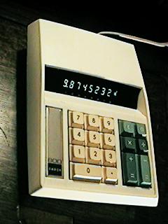
The Omron 800 Calculator
The Omron chip set, which became known as the ALPHA chip set, was completed in early 1971, and set a new record low-price benchmark for a highly integrated four-function calculator chip set. Omron packaged the chips into a compact and attractive desktop package, and in June of 1971 introduced the Omron 800. The machine was introduced at a price that was substantially lower any other calculator on the market at the time. Orders for the machines came rolling in like crazy. Along with selling the Omron-branded calculators, Omron also had packaged the ALPHA chip set on a simple and inexpensive circuit board that contained the power supply, clocking circuitry, and vacuum-fluorescent display driver circuitry. Omron offered this board as an OEM product to anyone that wanted to market their own calculator based Omron's technology. All that was needed was a cabinet, keyboard, and some vacuum fluorescent display tubes and a calculator was born. Japanese company Citizen jumped on Omron bandwagon, and marketed their machine as the Citizen 8. Commodore, who had built a calculator business buying calculators from Casio under contract, and putting Commodore badges on them, also signed on, marketing its version of the Omron machine as the Commodore C108. Nortec was cranking out the chip sets like hotcakes, because the demand created by these new low-cost calculators was insatiable. By mid-summer of 1971, Nortec Electronics had sold over 250,000 of the chip sets, and both Nortec and Omron were rolling in dough. Then, something happened.
Bob Norman, the founder of Nortec, made frequent trips to Japan to drum up business, along with keeping relations going with Nortec's existing Japanese customer base. During the times that Bob was away, he would put members of his executive staff in charge. During one trip to Japan, the executive that had been put in charge decided that it would be even more profitable for Nortec if the price of the Alpha chip set was increased slightly. Even a small increase in the price would translate to pretty big sales numbers because of the sheer volume of chips being produced. When Omron was notified about this price increase, they were furious. They contacted Bob Norman, outraged at what Norman's company had done to them. Norman didn't know what had happened, and when he found out, he too was furious at the actions of his underling. Unfortunately, the damage was done, and despite valiant efforts by Norman to correct this mistake, nothing could salvage the situation. The contract to develop the chip set that Nortec and Omron had engaged in gave Omron complete and exclusive rights to the design. Omron contacted the huge Japanese electronics firm Hitachi, which had very quickly developed its own advanced MOS LSI design and fabrication capabilities in the early 1970's. Hitachi quickly responded that they could build the chips for Omron at an even better price than originally quoted by Nortec. Omron immediately canceled the contract with Nortec and gave the chip design to Hitachi. Hitachi proceeded to manufacture the chips for Omron from that point on. The ALPHA designation was dropped, and the chips became the Hitachi HD32104, HD32105, and HD32106. This chip set was virtually identical in function to the Alpha chip set, but with one subtle change - the addition of a constant function. The chips were also packaged in plastic packages with tin-plated leads -- much less expensive than the ceramic packages with gold-plated leads that Nortec produced. The price decrease in the chip set allowed Omron to make a new OEM circuit board that cost even less, and supported a monolithic VF display module versus individual VF tubes, further reducing the cost of a complete calculator. A new version of the Omron 800 (the Omron 800K) was introduced that allowed Omron to yet again set a new low benchmark for the price of a basic electronic calculator. With the market success of the Omron 800K, a number of other manufacturers joined in on the gravy train, including Adler (the Adler 804, and Miida (the Miida MC840). Citizen continued their line, with the Citizen Eight Deluxe. All of these machines debuted in late 1971, and were solid market successes. The use of this low-cost basic calculator chip set allowed these manufacturers to dramatically undercut the prices charged for similar calculators by market-leading calculator manufacturers such as Sharp and Casio. These low-cost calculators triggered a round of price wars in the marketplace that reshaped the face of the calculator industry in a few short years.
An interesting side note is the significance of the model number of the Victor 3900. It happened that 3900 was the address of Victor's headquarters in Chicago. The street address was 3900 N. Rockwell (the building that Victor occupied is still there, currently occupied by Basic Wire and Cable). The idea behind using the company's address for the model number of this ground-breaking calculator was that this address would become synonymous with the expected market-changing success of the machine in the electronic calculator marketplace. As history would have it, the significance of "3900" was never recognized.
While history seems to have painted the Victor 3900 as a market failure, it in fact was quite successful as an example of ahead-of-the-state-of-the-art technology. As illustrated, the Victor 3900 paved the way for incredible advancement in the state-of-the-art in MOS Large Scale IC design and fabrication. Despite issues with the MOS IC process, something over 1000 of the Victor 3900 were made, and many of them provided years of reliable service. There are at least two existing Philco-Ford 3900s that are still fully functional to this day! The 3900 completely met the definition of what an electronic calculator was all about -- providing fast, silent, accurate and easy answers to mathematical problems. It dramatically exceeded the definition of an electronic calculator as far as the technology used to implement it was concerned. While not a commercial success, GM-e and its work for Victor Comptometer in developing the Victor 3900 refined a new technology that would forever alter the course of electronics. Both GM-e and Victor, as well as the people involved in these forward-looking companies, deserve significant historical recognition for their contributions made to advancing the state of the art in integrated circuit technology in a way that literally changed the world.